LAURITZ KNUDSEN / ELECTRICAL & AUTOMATION
Industrial signaling
Switch, signal and monitor. Components that bring control panels together.
EXPLORE THE COLLECTION
Built around your application.
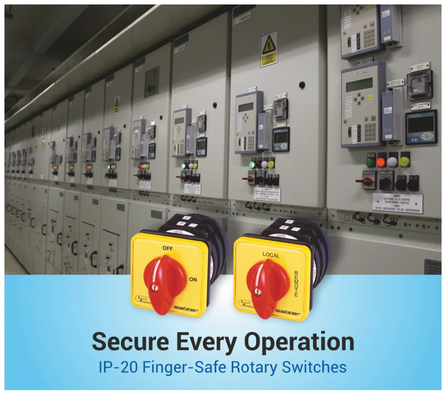
Rotary & cam switches
Operator switching for isolation, changeover, instrumentation and machine control.

Load break switches
On-load isolators and changeover switches for panel applications.
Panel cable ducts
Cable routing ducts and spare covers for control-panel wiring.
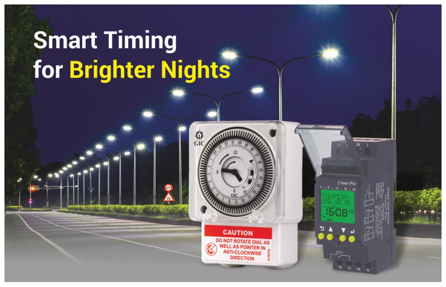
Timers & monitoring relays
Timing and monitoring components for industrial control circuits.
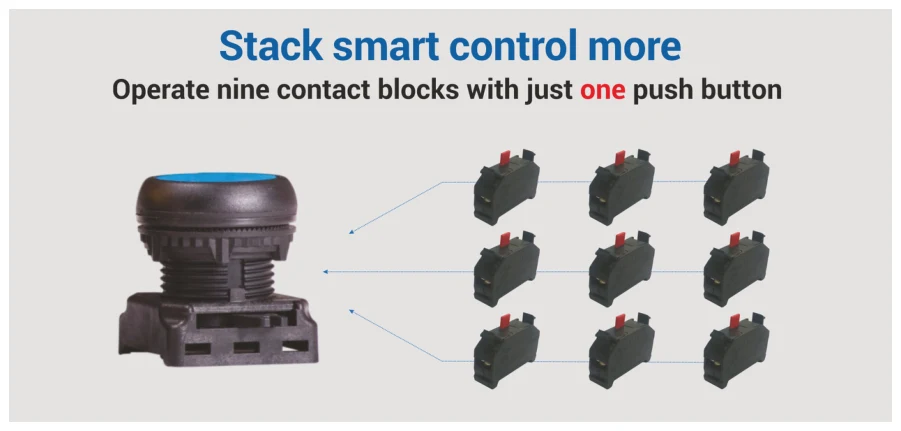
Push buttons & indicators
Gen Next operator controls, LED indicators and assembled stations.
MANUFACTURER REFERENCE / August 2026
Details, down to
the catalog number.
Browse the supplied specification pages. Published MRP is a dated manufacturer reference; request a current Nova quote and confirm the tax basis and pack size.
Industrial Signaling Products Pricelist (1).pdf ↗ · PDF pages 1–48
48 catalog pages
PDF page 1 Illustrated catalog page
Extracted reference text; use the original PDF to check column alignment, variants and price units.
This page is illustrated. Open the original PDF to view its contents.
PDF page 2 Illustrated catalog page
Extracted reference text; use the original PDF to check column alignment, variants and price units.
This page is illustrated. Open the original PDF to view its contents.
PDF page 3 Content
Extracted reference text; use the original PDF to check column alignment, variants and price units.
Content

Rotary Switches                                                                         01


Load Break Switches                                                                     13


Cable Ducts                                                                             16


Timing Devices, Supply Monitors & ELR                                                   21


Modular Remote Control Units                                                            29
Note :

Colour of HSN code signifies below
[Green colour : HSN code]
Current GST 18%, subject to changes as per Govt. notification


                                                               Lauritz Knudsen, 15.08.2026   3
PDF page 4 Illustrated catalog page
Extracted reference text; use the original PDF to check column alignment, variants and price units.
This page is illustrated. Open the original PDF to view its contents.
PDF page 5 Illustrated catalog page
Extracted reference text; use the original PDF to check column alignment, variants and price units.
This page is illustrated. Open the original PDF to view its contents.
PDF page 6 Rotary Switches
Extracted reference text; use the original PDF to check column alignment, variants and price units.
Rotary Switches

    Note: All mentioned prices are for Standard Mounting & Knob. Kindly reach our branch offices for details of other
    mountings & knobs.


    Cam Operated Rotary Switches [8536]

            OFF                       ON                       OFF
                  ON


                                                                                  Isolators Switches
                              OFF                     ON              ON


                                                               OFF                (ON-OFF Switches)

                                                  900 Operation
           600             900 Operation           Complete                                                              M.R.P. (`) Per Unit
         Operation
                                                    Rotation
                                                                           Description
     Cat. No.: Program Code (First 5 digits), Next 5 digits in () #
                                                                                          6A        10A       16A       25A       32A       40A       63A      100A      200A
                                                                                         (SAB13)   (SBB13)   (SCB03)   (SEB03)   (SFB03)   (SGB03)   (SIB03)   (SKB03)   (SNB03)

                                                                           1 Pole ON -
          61001                   61191                61195                              210       335       475       530       665       905      1055      4985      6445
                                                                              OFF
                                                                           2 Pole ON -
          61002                   61192                61198                              270       380       545       650       770      1085      1350      6240      8405
                                                                              OFF
                                                                           3 Pole ON -
          61003$                     -                     -                  OFF
                                                                                          285       460       985      1235      1375      1825      2615      8455      11010

             -                    61199                61197                              285       460       635       860       960      1265      1815      7690      10490
                                                                           4 Pole ON -
          61004                   61194                61196                              360       510       690      1035      1115      1435      2165      8895      12475
                                                                              OFF
    Note : Offered upto 12 Pole
           $ Motor Duty Switch (AC-3 Duty)


             0                        0                        1

                                                                                                Changeover Switches
                                                                                                (Local - Remote, Auto -
     1               2        1              2         2              2


                                      0                        1                                Manual Switches)


                                                   Without OFF
      With Center                   With
                                                    (900) with
          OFF                        OFF                                                                                 M.R.P. (`) Per Unit
                                                    Complete
         (600)                      (900)                                  Description
                                                     Rotation
     Cat. No.: Program Code (First 5 digits), Next 5 digits in () #
                                                                                          6A        10A       16A       25A       32A       40A      63A       100A      200A
                                                                                         (SAB13)   (SBB13)   (SCB03)   (SEB03)   (SFB03)   (SGB03)   (SIB03)   (SKB03)   (SNB03)


          61025                   61151                61037                 1 P 2W       270       425       605       665       745      1055      1430      6445      9325

          61026                   61152                61038                 2 P 2W       360       505       690       895      1035      1440      2165      9430      14210

          61027                   61153                61039                 3 P 2W       435       625       915      1350      1465      1815      2905      12220     18180

          61028                   61154                61040                 4 P 2W       540       730      1060      1780      1870      2195      3650      15435     22700


1     Lauritz Knudsen, 15.08.2026
PDF page 7 Phase Changeover (PS Series Switches)
Extracted reference text; use the original PDF to check column alignment, variants and price units.
Phase Changeover (PS Series Switches)
    OFF
                                                                                                                 M.R.P. (`) Per Unit
3         1       Cat. No.: Program Code (First 5 digits), Next 5 digits in () #        Description
                                                                                                       25A         32A       40A        63A
    2                                                                                                 (PEB03)     (PFB03)   (PGB03)    (PIB03)


                                            61060                                  1 P 3W with OFF     555         685      1005       1130


              Phase Changeover in SS enclosure

                                                                                                                 M.R.P. (`) Per Unit
                          Cat. No.                                        Description
                                                                                                       25A          32A      40A        63A
                                                                                                        (E)          (F)      (G)        (I)

                        M17TDYR.
                 72347P M17TDYR.                         PS Series Switches in SS enclosure            4690        4945      7295      7480

              Note : Prices are available on request for higher than 4 Pole ON-OFF version.
                     Please contact nearest E&A branch office for prices.
                     # For complete ordering code, Kindly refer Page No.10


                                                                                                                Lauritz Knudsen, 15.08.2026      2
PDF page 8 Spring Return Switches [8536]
Extracted reference text; use the original PDF to check column alignment, variants and price units.
Spring Return Switches [8536]


                            ON - OFF Spring Return Switches

                                                                                                                                    M.R.P. (`) Per Unit
                                                                   Cat. No.: Program Code (First 5 digits), Next 5 digits in ()
                             Description                                                                                                   16A
            OFF
                                                                                                                                          (SCB03)
                        S
                        T    1 P ON - OFF                                                      61351                                      1030
                        A
                        R
                        T    2 P ON - OFF                                                      61352                                      1080

                             3 P ON - OFF                                                      61353                                      1230

                             4 P ON - OFF                                                      61354                                      1440


                            Double Throw with Spring Return Switches

            OFF                                                                                                                     M.R.P. (`) Per Unit
     1              2                                             Cat. No.: Program Code (First 5 digits), Next 5 digits in () #
                             Description                                                                                                   16A
                                                                                                                                          (SCB03)

                             1 P 2W W/OFF Spring Return                                        61361                                      1080

                             2 P 2W W/OFF Spring Return                                        61362                                      1600

                             3 P 2W W/OFF Spring Return                                        61363                                      1740


                            One Side Spring Return Switches
            OFF
     1                                                                                                                              M.R.P. (`) Per Unit
                                                                  Cat. No.: Program Code (First 5 digits), Next 5 digits in () #
                        2
                             Description                                                                                                   16A
                                                                                                                                          (SCB03)

                             1 P 3W Spring Return - OFF from 1                                 61364                                       985

                             2 P 3W Spring Return - OFF from 1                                 61365                                      1440

                             3 P 3W Spring Return - OFF from 1                                 61369                                      1585


                            Spring Return Switches without OFF

             1
                                                                                                                                    M.R.P. (`) Per Unit
                                                                   Cat. No.: Program Code (First 5 digits), Next 5 digits in () #
                    2
                             Description                                                                                                   16A
                                                                                                                                          (SCB03)

                             1 P 2W Spring Return - from 2 to 1                                61371                                       985

                             2 P 2W Spring Return - from 2 to 1                                61372                                      1440

                             3 P 2W Spring Return - from 2 to 1                                61373                                      1585


                            Start Stop Spring Return Switches

                                                                                                                                    M.R.P. (`) Per Unit
                                                                   Cat. No.: Program Code (First 5 digits), Next 5 digits in () #
     STOP         START      Description                                                                                                   16A
                                                                                                                                          (SCB03)

                             1 P Start Stop Spring Return                                      61300                                      1230

                             2 P Start Stop Spring Return                                      61388                                      1440

                            Note: Prices for 25A rating are available on request.
                            # For complete ordering code, kindly refer Page No. 10


3    Lauritz Knudsen, 15.08.2026
PDF page 9 Multi Step Switches [8536]
Extracted reference text; use the original PDF to check column alignment, variants and price units.
Multi Step Switches [8536]


                                               Multi Step Switches with OFF
                                                                                                               M.R.P. (`) Per Unit
                                                                Cat. No.
                                                Description
                                                                   #          6A        10A       16A       25A       32A        40A       63A          100A      200A
                                                                            (SAB13)   (SBB13)    (SCB03)   (SEB03)   (SFB03)   (SGB03)    (SIB03)       (SKB03)   (SNB03)

                                                   1 P 3W        61060        315       480       630      PS Series Switches (Refer page no. 2)        6550      9950
                OFF


  3                           1       3 Way        2 P 3W        61080        435       555       765      1070       1145      1755       1975         9630      15215

                 2                                 3 P 3W        61100        630       745      1305      1585       1730      2345       3050         12575     19980

                                                   4 P 3W        61131        805       970      1585      1980       2170      3135       3670         15885     25055


                                                   1 P 4W        61061        370       435       915      1125       1240      1495       2035         9215       ***
                 0
                              1                    2 P 4W        61081        630       800      1080      1175       1375      2145       2380         15435      ***
                                      4 Way
  4                           2                    3 P 4W        61101        870      1020      1710      1980       2275      2735       3670         23260     30045
                 3

                                                   4 P 4W        61132       1055      1495      2185      2375       2535      3550       4225         32645     48970


                  0
                                                   1 P 5W        61062        405       560       970      1400       1415      1540       2190          ***      18700
   5                              1

                                      5 Way
                                                   2 P 5W        61082        730      1055      1405      1910       2245      2440       3055          ***       ***
   4                          2
                  3
                                                   3 P 5W        61102        970      1925      2440      2705       2985      3525       4140         30970      ***


                     0            1                1 P 6W        61063        530       700      1020      1410       1440      1590       2430          ***       ***

      6                           2   6 Way        2 P 6W        61083        870       ***      1495      2220       2575       ***       5120          ***       ***
      5              4            3
                                                   3 P 6W        61103       1215       ***      2805      3185       3435       ***        ***          ***       ***


      7              0            1                1 P 7W        61064        540       790      1100      1415       1495      1650       2550          ***       ***

      6                           2   7 Way        2 P 7W        61084        910       ***      1460      2230       2375      3495       4040          ***       ***
      5              4            3
                                                   3 P 7W        61104       1265       ***      2365      2935        ***      4760       5610          ***       ***


                     0    1
                                  2                1 P 8W        61065        615       860      1090      1945       2180      2600       4210          ***       ***
                                  3    8 Way
      8                           4                2 P 8W        61085        995       ***      1995        ***       ***       ***        ***          ***       ***
            7        6    5


                     0    1
                                  2                1 P 9W        61066        630       ***       ***        ***       ***       ***        ***          ***       ***
      9                           3    9 Way
      8                           4                2 P 9W        61086       1130       ***      2930        ***       ***       ***        ***          ***       ***
            7        6    5


                     01
      10                          2
                                                  1 P 10W        61067        730      1045      1535      3330        ***       ***        ***          ***       ***
      9                           3   10 Way
      8                           4               2 P 10W        61087       1170       ***       ***        ***       ***       ***        ***          ***       ***
            7        6    5


           11        0    1
      10                          2               1 P 11W        61068        870       ***      1395      3640        ***       ***        ***          ***       ***
      9                           3   11 Way
      8                           4               2 P 11W        61088       1325       ***       ***        ***       ***       ***        ***          ***       ***
            7        6    5

                                               ***Prices are available on request.
                                               # Program Code first 5 digits, Next 5 digits in (), For complete ordering code, kindly refer Page No.10

                                                                                                                                    Lauritz Knudsen, 15.08.2026             4
PDF page 10 Multi Step Switches without OFF
Extracted reference text; use the original PDF to check column alignment, variants and price units.
Multi Step Switches without OFF
M.R.P. (`) Per Unit
Cat. No.
Description
# 6A 10A 16A 25A 32A 40A 63A 100A 200A
(SAB13) (SBB13) (SCB03) (SEB03) (SFB03) (SGB03) (SIB03) (SKB03) (SNB03)
1 P 3W
61049 295 460 645 820 860 1400 1585 *** 10100
W/O OFF
1
2 P 3W
2 61069 435 695 900 1085 1630 1755 2065 9630 18180
W/O OFF
3 Way
3 P 3W
3 61089 630 860 1345 1585 1730 2345 3050 12575 20170
W/O OFF
4 P 3W
61120 805 970 1565 2020 2145 4990 5515 *** 26145
W/O OFF
1 P 4W
61050 330 500 770 990 1035 1530 2120 6550 10320
W/O OFF
1
2 P 4W
61070 490 755 915 1165 1290 1830 2380 10120 16345
W/O OFF
4 2 4 Way
3 P 4W
61090 675 800 1460 1870 2070 2390 3205 13330 22035
3 W/O OFF
4 P 4W
61121 935 1050 1700 2260 2405 3205 4270 16380 27890
W/O OFF
1 P 5W
61051 405 515 845 1115 1375 *** 2190 8410 ***
1
W/O OFF
5 Way 2 P 5W
2
61071 730 940 1170 1785 2245 *** *** *** 20710
W/O OFF
5
3 3 P 5W
61091 970 1925 2230 2450 2685 3015 4260 *** 26335
4
W/O OFF
1 P 6W
61052 425 845 930 1240 1415 1765 2235 9630 18860
6
1
2 W/O OFF
6 Way 2 P 6W
61072 855 990 1410 2215 2280 2440 3120 19190 24675
W/O OFF
5 3
4 3 P 6W
61092 1035 1805 2395 2645 2745 3190 4260 32645 51605
W/O OFF
1 P 7W
61053 530 790 1025 1470 *** *** *** 16970 ***
1
2 W/O OFF
7 Way 2 P 7W
7 3 61073 910 *** 1585 2260 *** *** 4755 *** ***
W/O OFF
6 5 4 3 P 7W
61093 1265 *** 2620 3430 *** *** 5730 *** ***
W/O OFF
1 P 8W
61054 540 930 1185 1495 1570 1835 2695 16125 ***
8 1 2 W/O OFF
8 Way 2 P 8W
7 3
61074 965 1480 1995 2360 2555 *** 5215 *** ***
W/O OFF
6 5
4
3 P 8W
61094 1350 *** 2850 3075 3145 3810 6020 *** ***
W/O OFF
1
1 P 9W
2
61055 630 *** 1395 *** *** *** *** *** ***
3
W/O OFF
4
9 Way
9 2 P 9W
5 61075 1065 *** 1980 *** *** *** *** *** ***
8 7 6 W/O OFF
1 2
3 1 P 10W
61056 680 995 1485 *** *** *** *** *** ***
W/O OFF
10 4 10 Way
2 P 10W
9 5 61076 1185 *** *** *** *** *** *** *** ***
8 7 6 W/O OFF
1
1 P 11W
2
3
11
61057 1255 *** *** *** *** *** *** *** ***
W/O OFF
10 4 11 Way
2 P 11W
9 5 61077 1425 *** *** *** *** *** *** *** ***
8 7 6 W/O OFF
1
1 P 12W
12 2
3
11
61058 1320 *** 1565 3765 4005 *** 5340 *** ***
W/O OFF
10 4 12 Way
2 P 12W
9 5 61078 1550 *** 4670 *** *** *** *** *** ***
8 7 6 W/O OFF
***Prices are available on request.
# Program Code first 5 digits, Next 5 digits in (), For complete ordering code, kindly refer Page No.10
5 Lauritz Knudsen, 15.08.2026PDF page 11 Instrumentation Selector Switches [8536]
Extracted reference text; use the original PDF to check column alignment, variants and price units.
Instrumentation Selector Switches [8536]


                     Ammeter Selector Switches (ASS)
                                                                                                      M.R.P. (`)
                     Description                                       Cat. No.            Amps
          OFF
                                                                                                       Per Unit

                     Line Currents with OFF with CT                61325 SAB13TDYR          6A           435
     B           R

                     Line Currents with OFF with CT                61325 SBB13TDYR          10A          450
           Y
                     Line Currents with OFF with CT                61325 SCB03TDYR          16A          685

                     Line Currents with OFF without CT             71000 SCB03TDYR          16A         2115
          OFF
     L           R   Direct Currents with OFF without CT           71000 SEB03TDYR          25A         2515

                     Direct Currents with OFF without CT           71000 SFB03TDYR          32A         3015
     B           Y
          OFF        Direct Currents with OFF without CT           71000 SGB03TDYR          40A         5320

                     Direct Currents with OFF without CT           71000 SIB03TDYR          63A         5610


                     Voltmeter Selector Switches (VSS)
                                                                                                      M.R.P. (`)
                     Description                                       Cat. No.            Amps
          OFF                                                                                          Per Unit

     BR         RY   Voltage between Phases with OFF               61312 SAB13TDYR          6A           320

                     Voltage between Phases with OFF               61312 SBB13TDYR          10A          415
          YB

                     Voltage between Phases with OFF               61312 SCB03TDYR          16A          610


                                                                                                      M.R.P. (`)
                     Description                                       Cat. No.            Amps
                                                                                                       Per Unit
          OFF
                     Voltage between Phases & Individual Phases
     RY         RN
                                                                   61313 SAB13TDYR          6A           570
                     to Neutral with OFF
     YB         YN

                     Voltage between Phases & Individual Phases
     BR         BN                                                 61313 SBB13TDYR          10A          800
                     to Neutral with OFF
                     Voltage between Phases & Individual Phases
                                                                   61313 SCB03TDYR          16A         1150
                     to Neutral with OFF


                                                                                                      M.R.P. (`)
     RY         RN   Description                                       Cat. No.            Amps
                                                                                                       Per Unit
     YB         YN
                     Voltage between Phase & Phase to Neutral
                                                                   61314 SBB13TDYR          10A          800
     BR         BN
                     without OFF

          OFF
                                                                                                      M.R.P. (`)
                     Description                                       Cat. No.            Amps
                                                                                                       Per Unit
     BN         RN
                     Voltage between Phase & Phase to Neutral
                                                                   61311 SAB13TDYR          6A           535
          YN
                     without OFF


                     Ammeter & Voltmeter Combined Switch
          OFF
                                                                                                      M.R.P. (`)
                     Description                                       Cat. No.            Amps
                                                                                                       Per Unit
     3           1

                     Voltage between Phases to Neutral & Current
                                                                   61338 SBB13TDYR          10A          845
           2         of that Phase


                                                                                     Lauritz Knudsen, 15.08.2026   6
PDF page 12 Illustrated catalog page
Extracted reference text; use the original PDF to check column alignment, variants and price units.
This page is illustrated. Open the original PDF to view its contents.
PDF page 13 Breaker Control Switches (Trip - Neutral - Close)
Extracted reference text; use the original PDF to check column alignment, variants and price units.
Breaker Control Switches (Trip - Neutral - Close)
                                                                    Contact             Mounting                                              M.R.P. (`)
                                                Rating                                   Type                      Cat. No.
                                                                  Arrangement                                                                  Per Unit

                                                 25A             1Trip + 1Close          Standard           73257SEB03PGBB                       1595

                                                 25A             1Trip + 1Close          Standard           73257SEB03PGYR                       1595

                                                 25A             1Trip + 1Close          Standard           73257SEB03PGGB                       1595

                                                 25A             1Trip + 1Close         Barrel Lock         73257SEB90PGBB                       2315

                                                 25A             2Trip + 2Close          Standard           72009SEB03PGBB                       1870

                                                 25A             2Trip + 2Close          Standard           72009SEB03PGYR                       1870

                                                 25A             2Trip + 2Close          Standard           72009SEB03PGGB                       1870

                                                 25A             2Trip + 2Close         Barrel Lock         72009SEB90PGBB                       2880

                                           Other option such as sequence inter lock (SIL) & lost motion device (LMD) available on request.
Motor Duty Switches

               OFF                         0                             Y                              0                                  1

                         ON      1                 2              O                            1                   1               0                2
                                                                  F
                                                                  F


                                                                                               2                   2


           61003                      61211                            61200                          61217                              61212

                                                                                                    M.R.P. (`) Per Unit
                                                       Cat. No.
 Description
                                                          #             16A         25A        32A           40A          63A          100A        200A
                                                                       (SCB03)     (SEB03)    (SFB03)       (SGB03)      (SIB03)       (SKB03)     (SNB03)

 ON - OFF Switch                                         61003          985         1235       1375         1825         2615          8455        11010

 FOR - OFF - REV Switch                                  61211          740         915        1085         3005         3670          8420        13580

 Star - Delta Switch                                     61200          985         1300       1625         2645         3380           ***         ***

 2 Speed for FOR - OFF - REV Switch                      61217           ***       2355^        ***         4175          ***           ***         ***

 2 Speed forward Switch                                  61212          1080        2140       2680         3565         4375          10535       12165

^ Supplied only with ball grip handle
# Program Code first 5 digits, Next 5 digits in ( ), For complete ordering code, kindly refer Page No.10

Switches in Enclosure

           0
                                     OFF               ON
  1                  2


      73393, 71913                             72244


 Description                                                                 Cat. No.                         Amps                 M.R.P. (`) Per Unit

 FOR - OFF - Rev in SS with ball grip handle                          73393SCM17BGXB                           16A                          1065

 FOR - OFF - Rev in SS with ball grip handle                          71913SEM17BGYR                           25A                          1620

 FOR - OFF - Rev in SS with ball grip handle                          71913SFM17BGYR                           32A                          2230

 3 Pole ON - OFF in SS                                                72244SEM17TDYR                           25A                          1405

 3 Pole ON - OFF in SS                                                72244SFM17TDYR                           32A                          1925

 3 Pole 2Way Without OFF in SS                                        61153SCM17TDYR                           16A                          1515

For any other rating requirement please contact nearest E&A branch office

                                                                                                                       Lauritz Knudsen, 15.08.2026           8
PDF page 14 Rotary Switch Accessories [8538]
Extracted reference text; use the original PDF to check column alignment, variants and price units.
Rotary Switch Accessories [8538]
                                                                                                                                       48 x 60

                                                                                                                                         48


                                                       SQ20

                                                                                                                               SQ 36
                                                                                                                                                 60

                                                                SQ32
    Front Plate Assembly                                                       Special Front Plate Assembly
                                                                  M.R.P. (`)                                                           M.R.P. (`)
    Description                      Cat. No.          Size                    Description                     Cat. No.      Size
                                                                   Per Unit                                                            Per Unit

    Front Plate for 6 to 16A        FP16SQ48       48 x 48             60      SPL IND Plates upto 16A        FPRT4860      48 x 60           130

    Front Plate for 25 & 32A        FP32SQ64       64 x 64             130     SPL IND Plates for 16 - 32A    FPRT6480      64 x 80           205

    Front Plate for 40 to 200A     FP200SQ88       88 x 88             185
                                                                               Script Plate (marking plate)
                                                                                                                                       M.R.P. (`)
                                                                               Description                     Cat. No.      Size
                                                                                                                                       Per Unit

                                                                               Script Plate for 6 - 16A        SPSQ48       48 x 48           35
                  Tear Drop    Flag Knob    Ball Grip         Lever Handle
                                                                               Script Plate for 16 - 32A       SPSQ64       64 x 64           45
    Handles & Knobs                                                            Script Plate for 40 - 200A      SPSQ88       88 x 88           50
                                                                  M.R.P. (`)   Script Plate for 6 - 16A       SPRT4816      48 x 16           10
    Description               Cat. No.          Size
                                                                  Per Unit
                                                                               Script Plate for 6 - 32A       SPRT6416      64 x 16           25
    Flag Handle for 16A       KNFHS2     48 x 48, 48 x 60              35
    Flag Handle for
                              KNFHS3     64 x 64, 64 x 80              60
    25 - 32A                                                                   Mounting Plates (used for Back Fixing Plate)
    Ball Handle for 16
                              HNBHS1     64 x 64, 64 x 80              170                                                                     M.R.P.
    - 32A
                                                                               Description                       Cat. No.       Size            (`)
    Ball Handle for                                                                                                                           Per Unit
                              HNBHS2 88 x 88, 104 x 104                185
    40 - 63A
                                                                               Rear MTG Plate for 6 - 16A       MPSQ48       48 x 48             25
    PG Handle for
                              HNPGS1     64 x 64, 64 x 80              205
    16 - 32A                                                                   Rear MTG Plate for 25 -32A       MPSQ64       64 x 64             45
    Lever Handle for                                                           Rear MTG Plate for 40 -63A       MPSQ88       88 x 88             115
                              HNLVS1 88 x 88, 104 x 104                270
    40 - 200A
                                                                               Rear MTG Plate for 80 -400A      MPSQ104 104 x 104                205
    Tear Drop for 6 - 16A KNTDS1         48 x 48, 48 x 60              35
    Tear Drop for                                                              DIN Rail Attachment upto 32A     B21DIN35                         185
                              KNTDS2     64 x 64, 64 x 80              60
    16 - 32A
    Tear Drop for
                              KNTDS3 88 x 88, 104 x 104                135
    40 - 400A


    Wall Type Mounting Boxes (upto 32A - maximum 4 Contacts)
                                                                                                             M.R.P. (`)
    Description                                                                                 Cat. No.
                                                                                                              Per Unit

    Plastic / ABS Enclosure B17 16A upto 3 Stage / 25A upto 2 Stage                            WMBABS          1295

    Aluminium Enclosure B17 16A upto 3 Stage / 25A upto 2 Stage                                 WMBAL          2135

    SS Enclosure M17 upto 32A - 4 Stage                                                         WMBSS           800
                                                                                                                              B31 PVC Enclosure
    Note : Switches to be order separately.

    Shrouding Cover (maximum 6 Contacts Round Type)
                                                                                                             M.R.P. (`)
    Description                                                                                 Cat. No.
                                                                                                             Per Unit

    Shrouding Cover for 6 - 10A                                                                 SHCS1           135

    Shrouding Cover for 16A                                                                     SHCS2           135

    Shrouding Cover for 25 - 32A                                                                SHCS3           190

    Shrouding Cover for 40 - 63A                                                                SHCS4           205

    Special Cover for Extended Termination 80 - 400A (maximum 2 Contact Stage)                  SHCS5          1550


9    Lauritz Knudsen, 15.08.2026
PDF page 15 Ordering Code for Rotary Switches
Extracted reference text; use the original PDF to check column alignment, variants and price units.
Ordering Code for Rotary Switches
                                     1.                                2.    3.                    4.                              5.                    6.
Example for :                 Programme Code                          Type Ampere                Mounting                         Knob                 Colour

25A 3 Pole

ON - OFF Switch      6        1        1         9          7          S          E         B           0     3            T             D         Y          R


1. Programme Code                                 2. Type Selection                                           3. Ampere Selection
                                  Programme
Programme                                            Type                                           Code      Ampere           Code      Ampere        Code
                                     Code

Isolators                           Pg. No. 1        S-Series (6 to 400A)                               S           6              A         100         K

Changeovers Switches                Pg. No. 1        Touch Proof (6 to 16A)                             T          10              B         125         L
                                                     Rear Access Termination                                       16              C         160         M
Phase Changeovers Switches          Pg. No. 2                                                           R
                                                     (16 to 63A)
                                                                                                                   20             D          200         N
Spring Return Switches              Pg. No. 3        Phase Selector Only for
                                                                                                        P
                                                     1 Pole 3 Way with OFF (25 to 63A)                             25              E         250         O
Multistep Switches with OFF         Pg. No. 4
                                                     DC Switches (16 to 500A)                           D          32              F         300         P
Multistep Switches without OFF      Pg. No. 5
                                                                                                                   40             G          400         Q
Instrumentation Switches            Pg. No. 6
                                                                                                                   50             H          500         R
Motor Control Switches              Pg. No. 8
                                                                                                                   63              I         600         S
Switches in SS Enclosure            Pg. No. 8
                                                         S Series           TP Series      RT Series Touch
                                                       Open Version        Touch Proof      Proof & Rear           80              J         800         T
Breaker Control Switches            Pg. No. 8                                               Termination


4. Mounting Style


5. Knob / Handle Selection                                                                Front Plate
   Code - TD      Code - FH       Code - PG      Code - BG            Code - LV             Standard Style        Frame Size                 Bigger Style


                                                                                            Current Ratings                              Current Ratings
                                                                                                                  SQ20
                                                                                              6/10 Amps                                        —
                                                                                                                          SQ32
   Tear Drop      Flag Knob       Pistol Grip     Ball Grip      Lever Handle

                                                                                             16/20 Amps            SQ36                      6/10 Amps
6. Color Combination Selection Table                                                                                      SQ48


                                                                                             25/32 Amps           SQ48                       16/20 Amps
    Code - YR        Code - GB             Code - BB            Code - AB
                                                                                                                          SQ64


                                                                                                S40 Amps
                                                                                                                  SQ68                       25/32 Amps
                                                                                                 & above
                                                                                                                          SQ88

 Yellow Front Plate Grey Front Plate Black Front Plate Aluminum Foil with
     Red Knob         Black Knob        Black Knob        Black Knob                                                                         S40 Amps
                                                                                                    -             SQ81
                                                                                                                                              & above
                                                                                                                          SQ104


                                                                                         Note : 1. For ratings of 6/10A, standard mounting
                                                                                                   style is B13
                                                                                                2. Single hole mounting equivalent of B03
                                                                                                   is B19 and B13 is B14.

                                                                                                                     Lauritz Knudsen, 15.08.2026                  10
PDF page 16 Mounting Feasibility
Extracted reference text; use the original PDF to check column alignment, variants and price units.
Mounting Feasibility
Feasibility
Mounting
Description 80/100/ 200/
Code 6/10A 16/20A 25/32A 40/63A
125A 400A
B03 Front Mounting, Standard Mounting plate
B13 Front Mounting with next size plate
Front Mounting 48 x 48 plate for 25/32A and 64 x 64 plate for
B00
40/63A
Single Hole Mounting 32 x 32 plate for 6/10A only 48 x 48 Plate
B19
for 16-32A
B14 Single Hole Mounting 48 x 48 plate for 6/10A
B33 Front Mounting with Round Padlock for 2 Position (for Isolators)
B30 Front Mounting with Rectangular Padlock 2 Position (for Isolators)
B63 Key Lockable type (Handle/Knob)
B90 Center Key Lock (Pistol grip Handle in black color only)
B02 Rear / (Back/Base) Mounting
B21 DIN Rail Mounting on 35 mm Rail 6-32 Amps
Rear / Base Mounting, Door Interlock + Rectangular Padlock
B32
(B30+B42)Base
B34 Rear / Base Mounting Door Interlock + Round Padlock (B33+B42)
Rear Mounting with Clutch Mechanism on Door
B41
(Door Open in all position without Interlock)
B42 Rear Mounting with Interlock Mechanism on Door
F47 Door Clutch, Mounting Plate at front
upto
B17 ABS Enclosure Max stages upto 3 upto 5 upto 5
4
B31 ABS Enclosure with Round Padlock (B33+B17) Max stages upto 2 upto 2 upto 2
upto
M17 Metal Enclosure Max stages upto 4 upto 3
4
upto
A17 Aluminium Enclosure Max stages upto 3 upto 2
4
B40 Single Hole Mounting with Padlock 48 x 48 Plate For 16-32A
B43 Single Hole Mounting with Center key 48 x 48 Plate for 16-32A
B45 Single Hole Mounting with Round Ring with Knob 16A-32A
DC Switches
› Available from 16A to 500A
› Used for railway coaches lighting & fan circuits switching, all DC power circuits - Railways,
Telecommunications & Power plants, Battery charging equipment
› Please contact nearest branch office for prices
11 Lauritz Knudsen, 15.08.2026PDF page 17 EB - GEN Changeover Switches [8536]
Extracted reference text; use the original PDF to check column alignment, variants and price units.
EB - GEN Changeover Switches [8536]
3 Pole EB - GEN Changeover Switches
M.R.P. (`) Per Unit
Description Cat. No. 25A 32A 40A 63A 80A 100A 125A
(E) (F) (G) (I) (J) (K) (L)
3 Pole C/O Front Panel
EBX31153B13BGYR 3259 3395 3960 4120 * * *
Mounting
3 Pole C/O Rear Mounting EBX31153MB42BGYR 3782 3919 4561 4704 8407 10519 13140
3 Pole C/O in SS Enclosure EBX31153SB31BGYR 4521 4645 5376 5536 * * *
3 Pole C/O Rear Mounting EBX31153B21BGYR 3782 3919 4561 4704 8407 10519 13140
3 Pole C/O Rear Mounting EBX31153MB34LHGB 3782 3919 4561 4704 8407 10519 13140
B13 Mounting
3 Pole C/O in Polycarbonate
EBX31153B31LBGYR 4521 4645 5376 5536 * * *
Enclosure
3 Pole C/O in SS Enclosure EBX31153SB31XLLHYR * * * * 11881 13978 16598
4 Pole EB - GEN Changeover Switches
M.R.P. (`) Per Unit
Description Cat. No. 25A 32A 40A 63A 80A 100A 125A
(E) (F) (G) (I) (J) (K) (L)
4 Pole C/O Front Panel
EBX31154B13BGYR 3782 3919 4645 4780 * * *
Mounting
4 Pole C/O Rear Mounting EBX31154MB42BGYR 4260 4424 5224 5438 10603 13268 16574
4 Pole C/O in SS Enclosure EBX31154SB31BGYR 5041 5237 6074 6290 * * *
MB42 Mounting 4 Pole C/O Rear Mounting EBX31154B21BGYR 4260 4424 5224 5438 10603 13268 16574
4 Pole C/O Rear Mounting EBX31154MB34LHYR 4260 4424 5224 5438 10603 13268 16574
4 Pole C/O in Polycarbonate
EBX31154B31LBGYR 5041 5237 6074 6290 * * *
Enclosure
4 Pole C/O in SS Enclosure EBX31154SB31XLLHYR * * * * 14075 16721 20048
Rating Selection Table
Ampere
Code ()
(A)
25 E
32 F
40 G
63 I
SB31 Enclosure
Note : SB 31 Enclosure for 25A to 63A ratings. B21 Mounting model is similar to B13 model
with links provided on the common side.
*** - Please contact nearest E&A branch office.
Lauritz Knudsen, 15.08.2026 12PDF page 18 Load Break Switches [8536]
Extracted reference text; use the original PDF to check column alignment, variants and price units.
Load Break Switches [8536]


     AC ON LOAD ISOLATORS

     › AC 23 Utilization category
     › Range from 16-125 Amps upto 8 pole
     › Multiple mounting options, ABS / Aluminium sheet steel
       enclosures / IP65 / NEMA Rated
     › Add on pole Power / Neutral & Auxiliary pole
     › Changover switches from 25-125 Amps upto 4 poles
       Confirms to IEC 60947-1 & 3, EN 60947-3, UL60947-4-1
                                                                                 B03                   MB34                  SB31M


     LB 3 Pole ON - OFF Switches

                                                             Can also                           M.R.P. (`) Per Unit
         Description                         Cat. No.       be given on
                                                              request     16A     20A    25A    32A     40A   63A     80A     100A   125A
                                                                          (C)      (D)    (E)    (F)    (G)    (I)     (J)     (K)    (L)

         Single Hole MTG Switch with
                                         LBX32300B19FPYR                  1118    1141    *      *       *      *      *       *       *
         Flag Knob
         Front Plate MTG with Flag
                                         LBX32300B40FPYR                  1088    1118    *      *       *      *      *       *       *
         Knob
         Front Panel MTG with B03
                                         LBX32300B03FLYR      32309       994     1019   1103   1141   1313   1407     *       *       *
         (48x48) Plate
         Front Panel MTG with B13
                                         LBX32300B13FLYR    32306/32309   994     1019   1103   1141   1313   1407    3557    4464   5606
         (64x64) Plate with Flag Knob
         Front Panel MTG with B13
                                         LBX32300B13BGYR      32309        *       *     1214   1255   1420   1500     *       *       *
         (64x64) Plate with BG Handle
         DIN Rail MTG Switch with
                                         LBX32300B23FLGB                   *       *     1103   1141   1313   1407     *       *       *
         Flag Knob
         Rectangular Pad Lock Switch
                                         LBX32300B30TDYR                   *       *     1336   1407   1544   1624     *       *       *
         with TDYR
         Round Pad Lock Switch with
                                         LBX32309B33RDYR                  1088    1117   1214   1255   1420   1500    3858    4814   6017
         RDYR
         Switch with B63 Lock & Key
                                         LBX32309B63TDYR                   *       *     1845   1929   2090   2145     *       *       *
         Version
         Base MTG Switch with DIL
                                        LBX32309MB34RDYR                  1738    1791   1929   2035   2119   2281    5139    6417   8021
         and Pad Lock
         Base MTG Switch with BG
                                        LBX32309MB42BGYR                  1738    1791   1929   2035   2119   2281    5139    6417   8021
         Handle
         Switch in Polycarbonate
                                        LBX32300B31SMRDYR                 2204    2270   2453   2516     *      *      *       *       *
         Enclosure - in B31SM
         Switch in Polycarbonate
                                        LBX32309B31MRDYR                   *       *      *      *     2751   2820     *       *       *
         Enclosure - in B31M
         Switch in Polycarbonate
         Enclosure - in B31L with       LBX32309B31LLHYR                   *       *      *      *       *      *     7239    8530   10123
         Leech Handle
         Switch in SS Enclosure - in
                                        LBX32309SB31LLHYR                  *       *      *      *       *      *     7239    8530   10123
         SB31L with Leech Handle

     Note : To make the complete cat number, replace “X” in the above cat.no with the appropriate current rating code.
           (Example: For LBX32300B19FPYR with a 16A rating ( 16A code = C), the complete code becomes LBC32300B19FPYR.)


13        Lauritz Knudsen, 15.08.2026
PDF page 19 LB 4 Pole ON - OFF Switches
Extracted reference text; use the original PDF to check column alignment, variants and price units.
LB 4 Pole ON - OFF Switches

                                                                        Can also                          M.R.P. (`) Per Unit
 Description                                          Cat. No.         be given on
                                                                         request      16A   20A     25A    32A     40A    63A    80A    100A 125A
                                                                                      (C)    (D)    (E)     (F)     (G)    (I)    (J)    (K)   (L)

 Single Hole MTG Switch with Flag Knob          LBX32400B19FPYR                      1390 1420       *      *        *     *      *      *     *

 Front Plate MTG with Flag Knob                 LBX32400B40FPYR                      1366 1390       *      *        *     *      *      *     *

 Front Panel MTG with B03 (48x48) Plate         LBX32400B03FLYR          32409       1268 1296 1408       1448 1694 1791          *      *     *
 Front Panel MTG with B13 (64x64) Plate
                                                LBX32400B13FLYR       32406/32409 1268 1296 1408          1448 1694 1791 4368 5480 6867
 with Flag Knob
 Front Panel MTG with B13 (64x64) Plate
                                                LBX32400B13BGYR          32409       1517 1557 1805       1888       *     *      *      *     *
 with BG Handle

 DIN Rail MTG Switch with Flag Knob             LBX32400B23FLGB                        *      *    1408   1448 1694 1791          *      *     *

 Rectangular Pad Lock Switch with TDYR          LBX32400B30TDYR                        *      *    1637   1706 1925 2010          *      *     *

 Round Pad Lock Switch with RDYR                LBX32409B33RDYR                      1366 1390 1517       1557 1805 1888 4464 5573 6968

 Switch with B63 Lock & Key Version             LBX32409B63TDYR                        *      *    2145   2230 2472 2531          *      *     *

 Base MTG Switch with DIL andPad Lock           LBX32409MB34RDYR                     2010 2064 2230       2335 2506 2669 5951 7430 9285

 Base MTG Switch with BG Handle                 LBX32409MB42BGYR                     2010 2064 2230       2335 2506 2669 5951 7430 9285

 Switch in Polycarbonate Enclosure - in B31SM   LBX32400B31SMRDYR                    2472 2546 2751       2818       *     *      *      *     *

 Switch in Polycarbonate Enclosure - in B31M    LBX32409B31MRDYR                       *      *      *      *      3133 3204      *      *     *
 Switch in Polycarbonate Enclosure - in
                                                LBX32409B31LLHYR                       *      *      *      *        *     *     8052 9545 11389
 B31L with Leech Handle
 Switch in SS Enclosure - in SB31L with
                                                LBX32409SB31LLHYR                      *      *      *      *        *     *     8052 9545 11389
 Leech Handle

 Auxiliary Contact                              FM / RM                               279   279     345    345      345   345    1019 1019 1019

 Add-on Contact Additional Pole                 FM / RM                               289   299     322    361      420   454    1190 1469 1634

Note : Standard packing upto 63A switches is 5 Nos.
Note : To make the complete cat number, replace “X” in the above cat.no with the appropriate current rating code.(Example: For
       LBX32300B19FPYR with a 16A rating ( 16A code = C), the complete code becomes LBC32300B19FPYR.)


                                                                                                                Lauritz Knudsen, 15.08.2026      14
PDF page 20 Ordering Code for Load Break and Changeover Switches
Extracted reference text; use the original PDF to check column alignment, variants and price units.
Ordering Code for Load Break and Changeover Switches
LB XXXXX XXXXX XX XX
Load Switch Programme Mounting Knob
Break Colour
Rating Code Options Options
Switch
Example
LB Switches, 63A, 3P, 9 O'clock, 4
hole front mounting, with metal shaft, LB I 32309 MB34 RD YR Description
yellow front plate, red round knob LB I 32309 MB34 RD YR
Yellow Front Plate/
Red Knob
64 x 64 Front Plate
Round Knob with
Padlock (R)
Metal Shaft with
Round Knob with
Padlock and Interlock
3Pole 9 O' Clock "OFF"
63A
Load Break Switch
Accessories LB I
R NC
32 Description
LB X X XX XXX
32A
Switch F-Front Mounting MC-Main Module 20 - 16A to 20A
Rating 32 - 25A to 32A Neutral Module
R-Rear Mounting NC-Neutral Module 63 - 40A to 63A Rear Mounting
80 - 80A
125 - 100A,
125A & 80A 63 A
AC-Auxiliary Module
Load Break Switch
Rating Selection Table
Ampere Code
(A) ()
16 C
20 D
25 E
32 F
40 G
63 I
80 J
100 K
125 L
*** Note : Please contact nearest E&A branch office.
15 Lauritz Knudsen, 15.08.2026PDF page 21 Cable Ducts [8538]
Extracted reference text; use the original PDF to check column alignment, variants and price units.
Cable Ducts [8538]

PVC Cable Ducts
› All ducts are ROHS compliant and FRLS                       › Also available in Zero Halogen


                                       Description                  1 meter                                      2 meter
       Type A
                                                         Cat.        M.R.P.            Min                         M.R.P.            Min
                                                                               Std.           Cat No.(Standard               Std.
                                         HxW         No.(Standard     (`)             Order                         (`)             Order
                                                                               Pkg.               slot Grey)                 Pkg.
                                                      slot Grey)    Per Unit           Qty                        Per Unit           Qty
                                        A 15 x 15    WWA1515SG         82      100    100      WWA1515SG2           164      64      64

                                        A 15 x 25    WWA1525SG        112      100    100      WWA1525SG2           224      64      64

                                        A 25 x 25    WWA2525SG        134      70      70      WWA2525SG2           268      48      48

                                        A 30 x 25    WWA3025SG        149      70      70      WWA3025SG2           298      48      48

                                        A 40 x 30    WWA4030SG        185      75      75      WWA4030SG2           370      32      32

                                        A 45 x 25    WWA4525SG        190      75      75      WWA4525SG2           380      40      40

                                        A 45 x 30    WWA4530SG        191      50      50      WWA4530SG2           382      32      32

                                        A 45 x 45    WWA4545SG        242      50      50      WWA4545SG2           484      18      18
 Specially designed      A Type
 Profiles of duct   * Snap fit cover
 and cover for                          A 45 x 60    WWA4560SG        291      50      50      WWA4560SG2           582      12      12
                    * Easy to remove
 fast and efficient
 locking.                               A 60 x 25    WWA6025SG        242      50      50      WWA6025SG2           484      18      18

                                        A 60 x 45    WWA6045SG        284      50      50      WWA6045SG2           568      18      18

                                        A 60 x 60    WWA6060SG        336      32      32      WWA6060SG2           672      12      12

                                       A 60 x 120    WWA60120SG       1142     18      90     WWA60120SG2          2284       8      80

                                        A 75 x 45    WWA7545SG        352      40      40      WWA7545SG2           704      12      12

                                        A 75 x 75    WWA7575SG        497      32      32      WWA7575SG2           994      12      12

                                        A 80 x 80    WWA8080SG        554      25      25      WWA8080SG2          1108      12      12

                                       A 100 x 100   WWA100100SG      897      18      18     WWA100100SG2         1794       8      40


                                                                                                        Lauritz Knudsen, 15.08.2026         16
PDF page 22 Description 1 meter 2 meter
Extracted reference text; use the original PDF to check column alignment, variants and price units.
Description                        1 meter                                     2 meter
          Type B                                                     M.R.P.            Min                        M.R.P.            Min
                                                     Cat. No.                  Std.              Cat. No.                   Std.
                                       WxH                            (`)             Order                        (`)             Order
                                                  (Standard slot)              Pkg.           (Standard slot)               Pkg.
                                                                    Per Unit           Qty                       Per Unit           Qty
                                     B 25 x 25    WWB2525SG           145      70      70     WWB2525SG2           290      36      36

                                     B 25 x 30    WWB2530SG           155      100    100     WWB2530SG2           310      36      36

                                     B 25 x 40    WWB2540SG           190      75      75     WWB2540SG2           380      36      36

                                     B 25 x 45    WWB2545SG           196      75     225     WWB2545SG2           392      36     108

                                     B 25 x 60    WWB2560SG           249      50      50     WWB2560SG2           498      18      18

                                     B 25 x 80    WWB2580SG           337      50      50     WWB2580SG2           674      18      18

                                     B 25 x 100   WWB25100SG          427      25      25     WWB25100SG2          854      18      18

                                     B 30 x 20    WWB3020UG           190      100    200     WWB3020UG2           380      36     180

                                     B 30 x 80    WWB3080SG           467      50     200     WWB3080SG2           934      18      90

                                     B 40 x 40    WWB4040SG           249      50      50     WWB4040SG2           498      18      18
            Non slip cover
         design of minimum           B 45 x 45    WWB4545SG           257      50      50     WWB4545SG2           514      18      18
          encumbrance and
                                     B 40 x 60    WWB4060SG           301      50      50     WWB4060SG2           602      18      18
           maximum grip
                                     B 40 x 80    WWB4080SG           356      50      50     WWB4080SG2           712      18      18

                                     B 40 x 100   WWB40100SG          447      25      25     WWB40100SG2          894      12      12

                                     B 45 x 20    WWB4520UG           197      75     225     WWB4520UG2           394      36     180

                                     B 50 x 100   WWB50100SG          513      30      90     WWB50100SG2         1026      12      60

                                     B 60 x 20    WWB6020UG           269      50     200     WWB6020UG2           538      18      90

                                     B 60 x 40    WWB6040SG           301      50      50     WWB6040SG2           602      18      90

                                     B 60 x 60    WWB6060SG           356      50      50     WWB6060SG2           712      12      12

               B Type                B 60 x 80    WWB6080SG           463      40      40     WWB6080SG2           926      12      12
          • Non - slip cover         B 60 x 100   WWB60100SG          610      30      30     WWB60100SG2         1220       8      8
          • Positive locking
                                     B 72 x 64    WWB7264SG           427      32      96     WWB7264SG2           854      18      90

                                     B 75 x 75    WWB7575SG           602      32      96     WWB7575SG2          1204       8      40

                                     B 75 x 100   WWB75100SG          630      25      75     WWB75100SG2         1260       8      40

                                     B 80 x 40    WWB8040SG           364      50     100     WWB8040SG2           728      12      60

                                     B 80 x 60    WWB8060SG           482      40      80     WWB8060SG2           964      12      60

                                     B 80 x 80    WWB8080SG           599      32      32     WWB8080SG2          1198      12      12

                                     B 80 x 100   WWB80100SG          674      24      24     WWB80100SG2         1348       8      8

                                     B 100 x 60   WWB10060SG          573      30      30     WWB10060SG2         1146       8      8

                                     B 100 x 80   WWB10080SG          674      25      25     WWB10080SG2         1348       8      8

                                 B 100 x 100      WWB100100SG         982      18      18     WWB100100SG2        1964       8      8

                                     B 120 x 80   WWB12080SG          953      18      90     WWB12080SG2         1906       8      40

                                 B 150 x 100      WWB150100SG         1225     12      48     WWB150100SG2        2450       4      40

                                 B 150 x 150      WWB150150SG         2663      8      80     WWB150150SG2        5326       2      40


     Note : 1) For any special colour request additional 10% will be charged on price. For cut length additional 10% will be charged.
            2) Thin / Unslot will be supplied on request. For thin slot replace the cat. number ending with SG by TG,
            For un slotted channel replace the cat. number ending with SG by UG. MRP will be same as standard slot.


17     Lauritz Knudsen, 15.08.2026
PDF page 23 Covers for FRLS Cable Duct
Extracted reference text; use the original PDF to check column alignment, variants and price units.
Covers for FRLS Cable Duct
(Cable duct comes with default covers, following are spare offerings)
                                                                                                                                 M.R.P. (`)
                                                       Description                            Cat. No.
                                                                                                                                  Per Unit

                                                 Cover for 15 mm A type                      CCA15SG                                     38

                                                 Cover for 25 mm A type                      CCA25SG                                     59

                                                 Cover for 30 mm A type                      CCA30SG                                     71

                                                 Cover for 45 mm A type                      CCA45SG                                     111

                                                 Cover for 60 mm A type                      CCA60SG                                     133

                                                 Cover for 75 mm A type                      CCA75SG                                     169

                                                 Cover for 80 mm A type                      CCA80SG                                     201

                                                 Cover for 100 mm A type                     CCA100SG                                    245

                                                 Cover for 25 mm B type                      CCB25SG                                     61

                                                 Cover for 30 mm B type                      CCB30SG                                     74

                                                 Cover for 40 mm B type                      CCB40SG                                     92

                                                 Cover for 45 mm B type                      CCB45SG                                     113

                                                 Cover for 50 mm B type                      CCB50SG                                     137

                                                 Cover for 60 mm B type                      CCB60SG                                     137

                                                 Cover for 72 mm B type                      CCB72SG                                     173

                                                 Cover for 75 mm B type                      CCB75SG                                     173

                                                 Cover for 80 mm B type                      CCB80SG                                     207

                                                 Cover for 100 mm B type                     CCB100SG                                    252

                                                 Cover for 120 mm B type                     CCB120SG                                    269

                                                 Cover for 150 mm B type                     CCB150SG                                    315


Slotting Styles (A & B Types)
                                                             2                                                               SR(Standard Restriction)
                                      2                                                R(Restricted)
                                                                                                                                     2
                                                                                         2


                                                                                                                                                     Restriction
                                                                                                       Restriction

                                     8 12                                                                                        8        20
                                                            46                     5          12.5
        Unslotted
          (US)                                                                                                           Standard Slot with Restriction(SR)
                                 Standard Slot            Thin Slot          Thin Slot with Restriction(R)


                                                          These products are manufactured by
Disclaimer
Every effort as to the correctness or sufficiency of the information and data contained in the catalogue is made. We however cannot
accept any liability for the accuracy or completeness of the information and data provided. No claims in this regard shall consequently
be accepted. We reserve the right to make changes, without prior notice, in the catalogue.
Products with CAT no. having, with or without, dot as suffix are same.


                                                                                                                     Lauritz Knudsen, 15.08.2026               18
PDF page 24 Illustrated catalog page
Extracted reference text; use the original PDF to check column alignment, variants and price units.
This page is illustrated. Open the original PDF to view its contents.
PDF page 25 Illustrated catalog page
Extracted reference text; use the original PDF to check column alignment, variants and price units.
This page is illustrated. Open the original PDF to view its contents.
PDF page 26 Timing Devices, Supply Monitors & ELR
Extracted reference text; use the original PDF to check column alignment, variants and price units.
Timing Devices, Supply Monitors & ELR


     Timers [9107]

                                                                                          Contact                         M.R.P. (`)
                           Type                 Time                Voltage                                    Cat. No.
                                                                                        Arrangement                        Per Unit

                                                              240 VAC/24 VAC/DC                                12ODT4        870

                           ON Delay        0.3 sec - 30 hrs   110 VAC/24 VAC/DC             1 C/O              11ODT4       1645

                                                              12 VDC                                           15ODT4       1350
        Micon 175
                           ON Delay &      0.1 sec - 100
                                                              240 VAC/24 VAC/DC             1 C/O              12WDTC       1355
                           Interval        hrs

                           Star Delta      3 sec - 120 sec    240 VAC             1 NO (Star)+1 NO (Delta)     12SDT0        980
                           Timer           3 sec - 30 sec     240 - 415 VAC       1 C/O (Star)+1 C/O (Delta)   14SDT1S      1735

                           Signal OFF      0.3 sec - 30 hrs   240 VAC/24 VAC/DC                                12RDT4       1275
                                                                                            1 C/O
                           Delay           0.3 sec - 30 hrs   12 VDC                                           15DDT4       1385

                           Multifunction   0.1 sec - 100                                    1 C/O              1CMDT0       2170
                                                              12 - 240 VAC/DC
                           Timer           hrs                                              2 C/O              1CMDTF       2315

                           Asymmetrical
                                           0.1 sec - 100
                           ON/OFF &                           12 - 240 VAC/DC               1 C/O              1CJDT0       2170
                                           hrs
                           OFF/ON

                                                              110 VAC/24 VAC/DC                                11BDT4       1620

                           One Shot        0.3 sec - 30 hrs   240 VAC/24 VAC/DC             1 C/O              12BDT4       1620

                                                              12 VDC                                           15BDT4       1695
                                           ON time :
                           Forward         6 sec -60 min
                           Pause Reverse   Pause time :       12 - 240 VAC / DC             2 C/O              1CZDTF       2315
                           Timer           0.1 sec-200 sec


     Pause time for Micon 175 star delta timer is 60 msec 1CMDT0 contains ON Delay, Impulse, Signal ON delay, Cyclic ON/
     OFF, Cyclic OFF/ON, Signal OFF Delay, Signal OFF/ON, Accumulative Delay ON signal, Impulse ON/OFF, Leading edge
     impulse, Trailing edge impulse, Leading edge Bistable


21    Lauritz Knudsen, 15.08.2026
PDF page 27 Timing Contact M.R.P. (`)
Extracted reference text; use the original PDF to check column alignment, variants and price units.
Timing                                          Contact                            M.R.P. (`)
                           Type                                             Voltage                                         Cat. No.
                                                      Range                                         Arrangement                           Per Unit
    Micon 225
                           ON Delay             0.1 sec - 10 hrs      24 - 240 VAC/DC                   2 C/O               2AODT5         2035

                           Star Delta                                 24 - 240 VAC/DC             1 NO (Star)+1 NO          2ASDT0         2125
                                                3 sec - 120 sec
                           Timer                                      240 - 415 VAC                    (Delta)              2BSDT0         2515

                           Multifunction                                                           2 C/O (1 Inst+1
                                                0.1s to 120 days      24 - 240 VAC/DC                                       2A8DT6         2280
                           Timer                                                                      Delayed)

                           Multifunction                              24 - 240 VAC/DC                                       2A5DT5         2255
                                                0.1 sec - 10 hrs                                        2 C/O
                           Multirange                                 240 - 415 VAC                                         2B5DT5         2715
                           Signal Base
                           Multi function       0.1 sec - 10 hrs      24 - 240 VAC/DC                   1 C/O               2ANDT0         2400
                           Multirange
                           Multifunction                              24 - 240 VAC/DC                                       2A6DT6         2415
                                                                                              2 C/O (1 Inst+1 Delayed
                           Timer 6              0.1 sec - 10 hrs
                           Functions                                  240 - 415 VAC                for 6th Mode)            2B6DT6         2460

                           True OFF Delay       0.6 sec - 600 sec     24 - 240 VAC/DC                   2 C/O               23GDT0         3315

                           Asymmetrical
                                                0.1 sec - 10 hrs      24 - 240 VAC/DC                   2 C/O               2AADT5         2555
                           ON/OFF

Pause time for Micon 225 star delta timer is 60 msec, 90 msec, 120 msec, 150 msec
Major timing functions
2A5DT5, 2B5DT5, 2A6DT6* and 2B6DT6* contains ON Delay, Interval, Cyclic ON/OFF, Cyclic OFF/ON, One Shot, ON
Delay, On Delay (1 Inst + 1 Delayed)*
2ANDT0 contains ON Delay, Interval, Signal ON Delay, Accumulative ON Delay, Signal OFF Delay, Signal OFF/ON Delay,
Leading edge impulse
2A8DT6 contains ON Delay, Impulse, Signal ON delay, Signal OFF delay, Step mode, One shot, Interval, Cyclic ON/OFF,
Cyclic OFF/ON, Signal OFF Delay, Accumulative Delay ON signal, Impulse ON/OFF.


 Digital Timer            Functions                Timer                  Voltage
                                                                                                    Contact
                                                                                                                         Cat. No.
                                                                                                                                        M.R.P. (`)
                                                                                                  Arrangement                            Per Unit
 DIGICON
                                                                     24 - 240 VAC/DC                  1 C/O              V0DDTS            2560
                          8 Functions       0.1 sec - 999 hrs
                                                                     24 - 240 VAC/DC                  2 NO               V0DDTD            2560

                                                                     24 - 240 VAC/DC                  1 C/O             V0DDTS1            2895
                          18 Functions      0.1 sec - 999 hrs
                                                                     24 - 240 VAC/DC                  2 NO              V0DDTD1            2895

V0DDTS and V0DDTD contains On Delay, Signal OFF Delay, Cyclic ON/OFF, Signal OFF/ON, Cyclic OFF/ON, Interval, Signal ON/OFF, One Shot output
V0DDTS1 and V0DDTD1 contains ON Delay, Cyclic OFF/ON, Cyclic ON/OFF, Impulse on energizing, Accumulative Delay ON Signal, Accumulative Delay on
Inverted signal, Accumulative Impulse ON signal, Signal ON Delay, Inverted Signal On delay, Signal OFF Delay, Impulse ON/OFF, Signal OFF/ON, Leading
edge impulse, Trailing edge impulse, Delayed impulse, Negative edge impulse.


 Motor Restart              Functions                       Timer                      Voltage
                                                                                                        Contact
                                                                                                                         Cat. No.
                                                                                                                                        M.R.P. (`)
                                                                                                      Arrangement                        Per Unit
 Timer
                                              Memory time Tm: 0.2 to 6 sec             110 VAC                           23LDT0            2670
                            Motor Restart
                                                                                                          1 C/O
                            Timer
                                              Delay time Td: 0.2 to 60 sec             240 VAC                           22LDT0            2670


                                                                                                                   Lauritz Knudsen, 15.08.2026         22
PDF page 28 Time Switches [9107]
Extracted reference text; use the original PDF to check column alignment, variants and price units.
Time Switches [9107]


          FM1 / Quartz                                            Product Description                               Cat. No.
                                                                                                                                M.R.P. (`)
                                                                                                                                 Per Unit


                                          FM1 / Quartz Daily          110 VAC - 240 VAC Base/DIN Mounting           J648B1        3470


        150 Hrs Battery Backup


     Digital Time                                                                                                                M.R.P.
                                                                  Product Description                               Cat. No.      (`)
     Switch                                                                                                                     Per Unit
                                                                  110 - 240 VAC 1 C/O Base/DIN 25 ON/OFF Each       67DDT0        3380

                                        Time Switch (Crono)       24 VDC 1 C/O Base/DIN 25 ON/OFF Each              6GHDT0        3995

                                                                  12 VDC 1 C/O Base/DIN 25 ON/OFF Each              69HDT0        4205

                                        Time Switch (Crono Pro)   110 - 240 VAC 2 C/O Base/DIN 50 ON/OFF Each       WT2DCDS       4810

                                                                  110 - 240 VAC 1 C/O Base/DIN 16 Pulse             67DDT9        3980
         Crono Pro     Crono / Pulse
                                        Time Switch (Pulse) *     24V DC 1 C/O Base /Din 16 Pulse                   6GHDT9        4490

                                                                  12V DC 1 C/O Base /Din 16 Pulse                   69HDT9        4720

     * For bell and siren application

     Astro                                                         Product Description                               Cat. No.
                                                                                                                                M.R.P. (`)
                                                                                                                                Per Unit

                                         Astro Mini    110 - 240 VAC 1 Phase - 2W 1 C/O , Base/Din                   T2DDT7       6570

                 Astro Pro Astro Mini    Astro Pro     110 - 240 VAC 1 Phase - 2W 2 C/O , Base/Din 50 ON/OFF Each   AS2DCDS       8150

     Note : Astro Mini / Astro Pro is used for lighting control based on sunrise / sunset timings by latitude / longitude
            settings primarily used in streetlight application


23     Lauritz Knudsen, 15.08.2026
PDF page 29 Supply Monitoring Devices [9032]
Extracted reference text; use the original PDF to check column alignment, variants and price units.
Supply Monitoring Devices [9032]
› SPP includes single phasing, phase sequence and phase unbalance monitoring with auto reset
Voltage & M.R.P.
Voltage Supply
Type Time delay Asymmetry Contact Cat. No. (`)
Monitoring Monitoring Type
Arrangement Per Unit
Relay
Series SM301 Single Phasing
65 VAC 415 VAC, 1 C/O MA51BC 1485
ON Delay 2 sec and Asymmetry 415 VAC, 2 C/O MC21B5 2175
(3Ph, Preventor (SPP*)
OFF Delay 7 sec
3W) Fail Safe 40 VAC
415 VAC, 1 C/O MA51BK 1485
Asymmetry
SM301 Phase loss OFF Delay 500 msec
(3Ph, monitoring Non and Recover Delay 30% Fixed 415 VAC, 1 C/O MA59B5 1710
3W) Fail Safe Type 2 Sec
Selectable ON
Delay (0 to 15 min) - MD71B9 2310
Selectable
SM 301 Under Voltage + Selectable ON 240 VAC,
Selectable Delay (0 to 15 sec) - 1 C/O
MD71BH 2310
Over Voltage
Selectable OFF
Delay (0 to 15 sec) - MD71BF 2705
Selectable ON Delay
Phase Asymmetry
(0 to 15 min) & OFF MG73B9 2820
10% fixed
Single Phasing Delay 5 sec
SM500 Preventor +
Selectable ON Delay
(3 Ph / Selectable Phase Asymmetry
(0 to 15 sec) & OFF MG73BH 2820
SM 500 1 Ph, Under Voltage + 10% fixed
Delay 5 sec 240 VAC,
4W) Selectable
Over Voltage Selectable OFF Delay 2 C/O
Phase Asymmetry
(0 to 15 sec) & ON MG73BF 2820
10% fixed
Delay 5 sec
SPP + UV/OV, with
Selectable ON (10 Sec) Phase Asymmetry
fixed UV (173 V) & MG73BR 2820
and OFF Delay (5 Sec) 20% fixed
OV (288 V)
SPP + Selectable ON Delay 5 sec and 415 VAC,
SM 500 UV + Selectable OV OFF Delay 5 sec, 94 VAC MAC04
3 Ph 4W, 2885
with Neutral with Neutral Loss 500ms-1s for Asymmetry D0100
Neutral fail 2 C/O
Loss Protection Protection
Selectable
SPP + Under Selectable ON Delay
Asymmetry MB53BM 2870
Voltage (80% of ) and OFF Delay 15 sec
(5% to 17%)
Selectable ON Delay 15 Phase Asymmetry
MG53BH 2870
sec & OFF Delay 5 sec 10%
SM501 Single Phasing Selectable OFF Delay Phase Asymmetry 415 VAC,
(3 Ph, Preventor + 15 sec & ON Delay MG53BF 2870
5 sec 10% 2 C/O
SM 501 3W) Selectable
Under Voltage + 65 VAC
ON Delay 5 sec and
MG53BI 2710
Digital Selectable OFF Delay 5 sec Asymmetry
VMR Over Voltage
ON Delay 3 min and
Phase Asymmetry
Series OFF Delay 5 sec UV
10%
MG53BO 2710
85% of OV 110% of
145-500 VAC
Single Phasing ( Line Voltage), DMS110 2745
Preventor + Power ON Delay Voltage: 1C/O
SM 800 Selectable (0 to 999 sec) , 5 to 99 VAC
(3PH/ 145-500 VAC
Under Voltage + OFF Delay (Default 60V),
( Line Voltage), DMS120 2975
3W, Selectable Over (0.1 to 999 sec) Percentage :
2C/O
4W) Voltage + Neutral & ON delay 2 to 50%
SM 800 Loss ( Applicable for (0.5 to 999 sec) (Default 10%) 85-300 VAC/DC
3P4W). (Auxiliary Supply) DMA220 3210
(P-N), 2 C/O
Phase loss + Phase Power ON delay
SM 600 Sequence + Phase (5s Fixed),ON delay
Voltage ±1% of set 500V -1000V AC
(3P, Asysmetery + UV (1-30 sec or Fixed), SMB110 13190
value 2 C/O
SM 600 3W) + OV + 3 phase OFF delay
(MMR) interruption (0.1 - 30 sec or Fixed)
Note : 3 Ph 3W - 3 Phase 3 Wire system; 3 Ph 4W - 3 Phase 4 Wire system.
Lauritz Knudsen, 15.08.2026 24PDF page 30 Voltage & M.R.P.
Extracted reference text; use the original PDF to check column alignment, variants and price units.
Voltage &                    M.R.P.
                                    Supply Monitoring                                                        Contact
     Voltage            Type
                                          Type
                                                                Time delay             Asymmetry                             Cat. No.     (`)
                                                                                                           Arrangement                  Per Unit
     Monitoring
                                                            ON Delay 500 msec &
     Relay                                                  OFF Delay 100 msec
                                                                                             –                               MK21D5      1775
     Series                        Phase loss +             ON Delay 500 msec &     Phase Asymmetry
                                                                                                                             MC21D5      1775
                                   Phase Sequence           OFF Delay 100 msec      (30% fixed)
                                   Monitoring
                                                            ON Delay 5 sec & OFF
                                                                                    Phase Asymmetry
                                                            Delay 100 msec                                                   MA21DN      2320
                                                                                    (5% to 15% variable)
                                                            (0 to 15s Selectable)
                                                                                                           208 - 480 VAC,
                                   Phase Loss + Phase
                                                                                                           1 C/O (Steps of
                       SM175       Sequence + Under
                                                            ON Delay 5 sec and                             208 - 220 -
                       (3 Ph,      Voltage + Over Voltage
                                                            Selectable OFF                   –             380 - 400 -       MD21DF      2380
                       3W)         monitoring (UV: -2% to
                                                            Delay (0 to 15 sec)                            415 - 440 -
                                   -20% of , OV: 2% to
                                                                                                           480 VAC)
                                   20% of )

                                                            Selectable ON Delay
                                   Phase Loss + Phase       (0.5 to 15 sec) and                                              MG21DH      2605
       SM175                       Sequence + Under         OFF Delay 5 sec
       3 Ph, 3W                                                                     Phase Asymmetry
                                   Voltage + Over Voltage
                                                            ON Delay 5s and         (10% fixed)
                                   (UV: -5% to -25% of ,
                                   OV: 5% to 25% of )       Selectable OFF                                                   MG21DF      2605


25   Lauritz Knudsen, 15.08.2026
PDF page 31 Current Monitoring relay (CMR)
Extracted reference text; use the original PDF to check column alignment, variants and price units.
Current Monitoring relay (CMR)
› Microprocessor based relay protects against Overload, Phase reverse, Phase loss, Phase unbalance faults
› Auto/ Manual reset selection
› Fail- safe protection with inbuilt CT upto 45A
› Inverse time model with underload, locked rotor protection and selectable trip class (10A, 10, 20, 30)
› Definite time model with underload and selectable start and trip time
Current & Contact M.R.P. (`)
Phase Type Cat. No.
Current Arrangement Per Unit
Monitoring 2 - 5A 1 C/O 17A422CB0
relay 3 - 9A, 1 C/O 17A122CB0
Inverse Time Current
Monitoring Relay 8 - 24A, 1 C/O 17A222CB0
15 - 45A, 1 C/O 17A322CB0
3 Phase 2 - 5A 1 C/O 17B422AA0 3225
3 - 9A, 1 C/O 17B122AA0
Definite Time Current
Monitoring Relay 8 - 24A, 1 C/O 17B222AA0
15 - 45A, 1 C/O 17B322AA0
Definite Type / Instant Trip 2 - 5A 1 C/O 17B422PA0
2 - 5A 1 C/O 17C412EB0
3 - 9A, 1 C/O 17C112EB0
Inverse Time Current
Monitoring Relay 8 - 24A, 1 C/O 17C212EB0
15 - 45A, 1 C/O 17C312EB0
1 Phase 3160
2 - 5A 1 C/O 17D412DA0
3 - 9A, 1 C/O 17D112DA0
Definite Time Current
Monitoring Relay 8 - 24A, 1 C/O 17D212DA0
15 - 45A, 1 C/O 17D312DA0
M.R.P. (`)
Relay Type Description Cat. No.
Per Unit
PTC 110 - 240 VAC, 2 C/O MJ83BK 3260
Thermistor 220 - 440 VAC, 2 C/O MJ93BK 3285
Relay Thermistor Relay 24 VAC/DC, 2 C/O MJA3BK 3815
Series
110 - 240 VAC, 1 C/O MJ81BK 3015
220 - 440 VAC, 1 C/O MJ91BK 3060
Hour Meter & Counter [9029]
M.R.P. (`)
Hour Meters Product Description Cat. No.
Per Unit
HM36, 85 - 265 VAC Flush Mounting LA25F1 1245
HM 36, 10 - 80 VDC Flush Mounting LD17F1 1885
HM36, 92 - 264 / 270 - 460 VAC Base - DIN Mounting 30A6B1 1355
HM36, 10 - 80 VDC Base/DIN Mounting 30D1B1 1885
Digital Hour Meter/Digital Counter (Resettable) ZFB 2260
Hour Meter / Counter
Lauritz Knudsen, 15.08.2026 26PDF page 32 Earth Leakage Relay [9032]
Extracted reference text; use the original PDF to check column alignment, variants and price units.
Earth Leakage Relay [9032]


      Earth Leakage                   Current                                     Voltage &
                                                                                                                          M.R.P.
                                                        Type                                                  Cat. No.     (`)
      Relays                          Range                                  Contact Arrangement
                                                                                                                         Per Unit
                                                                     110 - 240 VAC/DC,
                                                                                                            17K716QF4N    5745
                                                                     1 C/O (Pre-alarm) + 1 C/O (Fault)
                                                                     110 - 240 VAC/DC,
                                                  Panel mounted      1 C/O (Pre-alarm) + 1 C/O (Fault)      17K716QF4M    8260
                                                  (96 x 96 mm)       with RS 485
                                                  Earth Leakage      240 - 415 VAC/DC,
                                                  Relay                                                     17K726QF4N    5745
          96 x 96 mm                                                 1 C/O (Pre-alarm) + 1 C/O (Fault)
          Earth Leakage                                              240 - 415 VAC/DC,
          Relay                                                      1 C/O (Pre-alarm) + 1 C/O (Fault)      17K726QF4M    8260
                                                                     with RS 485

                                                                     110 - 240 VAC, 110 VDC, Manual reset   17G715GF2


                                                                     220 - 415 VAC, 220 VDC, Manual reset   17G745GF2
                                                  DIN mounted
                                                  Earth Leakage                                                           5155
                                                  Relay              110 - 240 VAC, 110 VDC, Auto reset     17G715KF2
          DIN Mounted
          Earth Leakage
          Relay
                                                                     220 - 415 VAC, 220 VDC, Auto reset     17G745KF2
                                     30mA - 30A
                                                                     38 mm ID                               17H7NNHN3     1770

                                                                     57 mm ID                               17H7NNIN3     2385
                                                  CBCT
                                                  (moulded case)     70 mm ID                               17H7NNQN3     2720
                                                  for Type
                                                                     92 mm ID                               17H7NNJN3     2970
                                                  A & AC Current
               CBCT                                                  120 mm ID                              17H7NNLN3     3100

                                                                     210 mm ID                              17H7NNKN3     5845

                                                                     38 mm ID                               17H7NNRN3     1325

                                                  CBCT               57 mm ID                               17H7NNVN3     1480
                                                  (moulded case)     70 mm ID                               17H7NNSN3     1570
                                                  for Type
         Rectangular CBCT                         AC Current         92 mm ID                               17H7NNTN3     2105
                                                                     120 mm ID                              17H7NNUN3     2435

                                                  Rectangular CBCT    300 x 50 mm ID                        17H9NNWN0    11680
                                                  (moulded case)
                                                  for Type AC Current 350 x 150 mm ID                       17H9NNXN0    14200

     › CBCT for Type AC : For applications with sinusoidal alternating current from 30mA to 30A.
     › CBCT for Type A and AC : For applications with sinusoidal alternating current (from 30mA to 30A) & pulsating DC
       current (from 30mA to 3A).
     › Please contact nearest branch office for requirements of higher dimension CBCTs.


                                                                      These products are manufactured by
     Disclaimer for Timing Devices and Supply Monitors                                                        www.gicindia.com
     Every effort as to the correctness or sufficiency of the information and data contained in the catalogue is made. We
     however cannot accept any liability for the accuracy or completeness of the information and data provided. No claims
     in this regard shall consequently be accepted.
     We reserve the right to make changes, without prior notice, in the catalogue.
     Products with CAT no. having, with or without, dot as suffix are same.

27     Lauritz Knudsen, 15.08.2026
PDF page 33 Illustrated catalog page
Extracted reference text; use the original PDF to check column alignment, variants and price units.
This page is illustrated. Open the original PDF to view its contents.
PDF page 34 Modular Remote Control Units
Extracted reference text; use the original PDF to check column alignment, variants and price units.
Modular Remote Control Units
Note : All Cat.No. to be ordered in multiple of Standard Packing : 10, Except for Push Button Stations.
Gen Next Series
Gen Next Pro LED Indicator [8531]
› Surface Mounted Device LED technology › Low Power consumption < 1W › Surge & Low Voltage Glow Protection (LVGP)
Colour Voltage M.R.P. (`)
Description Cat. No.
(4th Digit) (5th, 6th, 7th & 8th Digit) Per Unit
012C - 12 VAC/DC
Ø22.5 mm 024C - 24 VAC/DC
030C - 30 VAC/DC 185
R-Red 048C - 48 VAC/DC
G-Green 064C - 64 VAC/DC 318
Gen Next Pro 110A - 110 VAC
Y-Yellow
LED Indicator EPL 110D - 110 VDC Blue & White
A-Amber
22.5 mm 240A - 240 VAC
B-Blue 220D - 220 VDC
W-White
232
415A - 415 VAC 392
Blue & White
R-Red
G-Green 216
New Gen Next Pro 012C - 12 VAC/DC
Y-Yellow 024C - 24 VAC/DC
LED Indicator SPL
A-Amber 110C - 110 VAC/DC
16 mm 240A - 240 VAC 359
B-Blue
W-White Blue & White
Note * : LED Indicator for Flame Proof Panel application available on request.
Universal LED Indicator [8531]
Colour Voltage M.R.P. (`)
Description Cat. No.
(8th Digit) (9th, 10th, 11th & 12th Digit) Per Unit
Gen Next Pro
Ø22.5 mm
Universal LED Indicator R-Red
Gen Next
G-Green 551
Pro
Y-Yellow
Universal EPL 224C-24 to 240V AC/DC
A-Amber 661
LED B-Blue Blue & White
indicator W-White
29 Lauritz Knudsen, 15.08.2026PDF page 35 Gen Next Push Button & Selector Actuators Ø 22.5 mm [8538]
Extracted reference text; use the original PDF to check column alignment, variants and price units.
Gen Next Push Button & Selector Actuators Ø 22.5 mm [8538]
› Snap Mounting with compact contact blocks (EC1C & EC2C) › Max 3 row x 3 column stackable contact blocks
Colour M.R.P. (`)
Description Cat. No.
(4th Digit) Per Unit
R-Red
G-Green
Ø30.2
C-Black
8.25 Y-Yellow
Flush Head EMNFD1 W-White
118
Ø22.5
B-Blue
A-Amber
F-Gray
R-Red
Ø30.2
G-Green
C-Black
8.25 19.65
Projecting Head Y-Yellow
EMNPD1 W-White
119
Ø22.5
Push Function
B-Blue
A-Amber
F-Gray
Mushroom Head R-Red
G-Green
‘Push - Turn EMNMH1 C-Black
231
Function’ Y-Yellow
R-Red
Mushroom Head G-Green
EMNMD1 C-Black 168
‘Push - Function’
Y-Yellow
2 Position
Non Spring Return
0
1
EP09SK000000 327
Spring Return
0
1
EP09SI000000
3 Position R-Red
G-Green
Symmetric Head Non Spring Return
0
1 2
EP09SL000000 C-Black
W-White
Spring Return
0
1 2
EP09SJ000000 346
Spring Return L. H.
0
1 2
EP09SM000000
Spring Return R. H.
0
1 2
EP09SN000000
2 Position
Non Spring Return
0
1
EMNLK1 327
0
1
Spring Return
EMNLI1
3 Position
R-Red
Lever Head Non Spring Return W-White
0
1 2
EMNLL1 C-Black
Spring Return
0
1 2
EMNLJ1 346
Spring Return L. H.
0
1 2
EMNLM1
Spring Return R. H.
0
1 2
EMNLN1
Lauritz Knudsen, 15.08.2026 30PDF page 36 Gen Next Push Button & Selector Actuators Ø 22.5 mm [8538]
Extracted reference text; use the original PDF to check column alignment, variants and price units.
Gen Next Push Button & Selector Actuators Ø 22.5 mm [8538]
Colour M.R.P. (`)
Description Cat. No.
(4th Digit) Per Unit
2 Position
0
1 Non Spring Return
EP09KK000000
0
1
Spring Return
EP09KI000000
471
3 Position
50.2 Lock & Key
8.25
0
Non Spring Return C-Black
Rotary Type 1 2
EP09KL000000
Ø22.5
1
0
2
Spring Return
EP09KJ000000
1
0
2 Spring Return L. H.
EP09KM000000
491
1
0
2 Spring Return R. H.
EP09KN000000
Push Pull EG02MG0 R-Red 452
Mushroom Head
Lock And Key EG02MQ0R00 R-Red 512
Actuator
Twin Touch
with Black EG02TD0I - 234
centre strip
Note : 1. Actuators & Selector Actuators with black ABS collar are offered as Standard
2. Actuators (except Mushroom Head Push - Pull Actuators) are also available with chrome plated ABS & Brass collar
Non-Illuminated Actuator
- For PU Coated ABS Collar replace 7th digit 1 by 2 eg. : EMNPD 2
- For Brass Metal Collar replace 7th digit 1 by 3 eg. : EMNPD 3 (Please contact nearest branch office for MRP)
lluminated Actuator
- For PU Coated ABS Collar replace 4th digit 3 by 5 eg. : EG0 5 ***
- For Brass Metal Collar replace 4th digit 3 by 7 eg. : EG0 7 *** (Please contact nearest branch office for MRP)
Brass Metal Coller Push Button
0 1 0
Note * : In 2 position selector actuator, for operating style replace 6th digit from K to R and for operating style 1
replace 6th digit from K to T
31 Lauritz Knudsen, 15.08.2026PDF page 37 Gen Next Illuminated Push Button Actuators [8531]
Extracted reference text; use the original PDF to check column alignment, variants and price units.
Gen Next Illuminated Push Button Actuators [8531]
› Snap Mounting with compact contact blocks (EC1C & EC2C)
Voltage
Colour M.R.P. (`)
Description Cat. No. (9th , 10th, 11th
(8th Digit) Per Unit
&12th Digit)
Ø30.2 R-Red 012C - 12 VAC/DC
024C - 24 VAC/DC
8.25 G-Green
030C - 30 VAC/DC 333
Y-Yellow 048C - 48 VAC/DC
Ø22.5
Flush Head EG03FDL A-Amber 064C - 64 VAC/DC
110A - 110 VAC
B-Blue 110D - 110 VDC 615
240A - 240 VAC
W-White 220D - 220 VDC Blue and White
R-Red 012C - 12 VAC/DC
G-Green 024C - 24 VAC/DC
Ø30.2
Projecting 030C - 30 VAC/DC 333
Y-Yellow
Head 048C - 48 VAC/DC
8.25 19.65 EG03PDL A-Amber 064C - 64 VAC/DC
(Push 110A - 110 VAC
Ø22.5
Function) B-Blue 110D - 110 VDC 615
240A - 240 VAC Blue and White
W-White
220D - 220 VDC
2 Position
0
1 Non Spring Return
EG03SKL 012C - 12 VAC/DC 486
R-Red
0
024C - 24 VAC/DC
Selector 1
Spring Return G-Green 030C - 30 VAC/DC
Actuator EG03SIL Y-Yellow 048C - 48 VAC/DC
064C - 64 VAC/DC
with LED 3 Position A-Amber 110A - 110 VAC
holder B-Blue 110D - 110 VDC
0
1 2
Non Spring Return 240A - 240 VAC 724
W-White
EG03SLL 220D - 220 VDC
Blue and White
0
1 2 Spring Return
EG03SJL
012C - 12 VAC/DC
024C - 24 VAC/DC
030C - 30 VAC/DC
Twin Touch 048C - 48 VAC/DC
Y- Yellow
with EG03TDL 064C - 64 VAC/DC 417
A-Amber 110A - 110 VAC
Led Holder
110D - 110 VDC
240A - 240 VAC
220D - 220 VDC
Note* : 1) In 2 position selector actuator, for operating style replace 6th digit from K to R and for operating style
0 1
replace 6th digit from K to T.
0
1
2) Assembly comes with LED holder. Please order contact block EC1C and EC2C separately.
Lauritz Knudsen, 15.08.2026 32PDF page 38 GEN NEXT Metal Push Button & Selector Actuator [8538]
Extracted reference text; use the original PDF to check column alignment, variants and price units.
GEN NEXT Metal Push Button & Selector Actuator [8538]
› Snap Mounting with compact contact blocks (EC1C & EC2C)
M.R.P. (`)
Description Cat. No. Colour
Per Unit
EM27FD0000
Ø30.2
EM27FD0000 R-Red
8.25
G-Green
EM27FD0000
C-Black
Ø22.5
Flush head EM27FD0000 Y-Yellow 124
W-White
EM27FD0000
B-Blue
EM27FD0000 A-Amber
EM27FD0000
2 Position
0
Non Spring Return EM27SK0000 1
368
0
Spring Return EM27SI0000 1
3 Position
Symmetric Head 0
C-Black
Non Spring Return EM27SL0000
1 2
0
Spring Return EM27SJ0000 1 2
416
0
Spring Return L.H. EM27SM0000
1 2
0
Spring Return R.H. EM27SN0000 1 2
2 Position
0
Non Spring Return EM27KK0000 1
505
0
Spring Return EM27KI0000 1
3 Position
50.2 Lock & Key 0
C-Black
8.25 Non Spring Return EM27KL0000
1 2
0
Ø22.5 Spring Return EM27KJ0000 1 2
560
0
Spring Return L.H. EM27KM0000 1 2
0
Spring Return R.H. EM27KN0000
1 2
EM27MH0000 R-Red
Mushroom Head-Push Turn 281
EM27MH0000 G-Green
Mushroom Head-Push Function EM27MD0000 R-Red 185
33 Lauritz Knudsen, 15.08.2026PDF page 39 GEN NEXT Metal Illuminated Push Button Actuator [8531]
Extracted reference text; use the original PDF to check column alignment, variants and price units.
GEN NEXT Metal Illuminated Push Button Actuator [8531]
M.R.P. (`)
Description Cat. No. Colour (8 Digit) Voltage (9 , 10 , 11 & 12 Digit)
Per Unit
R-Red 012C - 12 V AC/DC
G-Green 024C - 24 V AC/DC
422
Y-Yellow 030C - 30 V AC/DC
Ø 30.2 A-Amber 048C - 48 V AC/DC
8.25
Illumnated 064C - 64 V AC/DC
EM28FD0
Ø22.5 Flush head
110A - 110 V AC
W-White 110D - 110 V DC 871
B-Blue
240A - 240 V AC
220D - 220 V DC
Gen Next Modular Contact Blocks [8538]
M.R.P. (`)
Description Cat. No. Colour Voltage
Per Unit
‘NO’ Block EC1C – – 93
‘NC’ Block EC2C – – 93
Spare for Gen Next Series [8531]
M.R.P. (`)
Description Cat. No. Colour Voltage
Per Unit
R-Red 012C - 12 VAC/DC
G-Green 024C - 24 VAC/DC
250
Y-Yellow 030C - 30 VAC/DC
A-Amber 048C - 48 VAC/DC
LED Holder
for Gen Next 064C - 64 VAC/DC
EG08HOL
illuminated
actuator series 110A - 110 VAC
498
B-Blue
110D - 110 VDC Blue and
W-White
White
240A - 240 VAC
220D - 220 VDC
Note : Contact blocks and LED holder are same for Gen next and Gen next META series
Lauritz Knudsen, 15.08.2026 34PDF page 40 Gen Next entegral Actuator [8536]
Extracted reference text; use the original PDF to check column alignment, variants and price units.
Gen Next entegral Actuator [8536]
› With inbuilt contact arrangement › Contact rating 6A @ 240AC
Contact Configuration Colour M.R.P. (`)
Description Cat. No.
(3rd Digit) (4th Digit) Per Unit
1 - 1 NO R-Red 183
Ø30.2 2 - 1 NC G-Green
8.25 Y-Yellow
Flush Head EEFD1 3 - 1 NO + 1 NC W-White
Ø22.5
4 - 2 NO B-Blue 265
A-Amber
5 - 2 NC
C-Black
1 - 1 NO R-Red 183
Ø30.2 2 - 1 NC G-Green
Y-Yellow
8.25 19.65
Projecting Head
EEPD1 3 - 1 NO + 1 NC W-White
Push Function
Ø22.5
4 - 2 NO B-Blue 265
A-Amber
5 - 2 NC
C-Black
1 - 1 NO
266
2 - 1 NC
R-Red
Mushroom Head G-Green
EEMH1 3 - 1 NO + 1 NC
Push - Turn Y-Yellow
4 - 2 NO C-Black 362
5 - 2 NC
1 - 1 NO
226
2 - 1 NC
R-Red
Mushroom Head G-Green
EEMD1 3 - 1 NO + 1 NC
Push - Function Y-Yellow
4 - 2 NO C-Black 307
5 - 2 NC
1 - 1 NO
2 Position 366
2 - 1 NC
R-Red
0
Non Spring Return G-Green
1
3 - 1 NO + 1 NC (Left NO)
EESK1 W-White
4 - 2 NO 449
C-Black
0
1
Spring Return 5 - 2 NC
EESI1 6 - 1 NO + 1 NC (Right NO)
3 Position
Symmetric Head
Actuator 1
0
2 Non Spring Return
EESL1
3 - 1 NO + 1 NC (Left NO) R-Red
1
0
2
Spring Return 4 - 2 NO G-Green
EESJ1 5 - 2 NC 462
W-White
1
0
2 Spring Return L. H. 6 - 1 NO + 1 NC (Right NO) C-Black
EESM1
1
0
2 Spring Return R. H.
EESN1
1 - 1 NO
2 Position 366
2 - 1 NC
R-Red
0
1 Non Spring Return 3 - 1 NO + 1 NC (Left NO) G-Green
EELK1 4 - 2 NO W-White
C-Black 449
Spring Return 5 - 2 NC
0
1
EELI1 6 - 1 NO + 1 NC (Right NO)
3 Position
Lever Head 1
0
2 Non Spring Return
EELL1
3 - 1 NO + 1 NC (Left NO) R-Red
1
0
2 Spring Return 4 - 2 NO G-Green
EELJ1 5 - 2 NC 462
W-White
1
0
2 Spring Return L. H. 6 - 1 NO + 1 NC (Right NO) C-Black
EELM1
1
0
2 Spring Return R. H.
EELN1
35 Lauritz Knudsen, 15.08.2026PDF page 41 Gen Next entegral Actuator [8536]
Extracted reference text; use the original PDF to check column alignment, variants and price units.
Gen Next entegral Actuator [8536]
Contact Configuration Colour M.R.P. (`)
Description Cat. No.
(3rd Digit) (4th Digit) Per Unit
2 Position 1 - 1 NO
469
2 - 1 NC
Non Spring Return
EEKK1 3 - 1 NO + 1 NC (Left NO) C-Black
4 - 2 NO
Spring Return 560
5 - 2 NC
EEKI1
6 - 1 NO + 1 NC (Right NO)
Lock & Key 3 Position
50.2
8.25 Rotary Type Non Spring Return
EEKL1
Ø22.5
3 - 1 NO + 1 NC (Left NO)
Spring Return
4 - 2 NO
EEKJ1 C-Black 573
5 - 2 NC
Spring Return L. H. 6 - 1 NO + 1 NC (Right NO)
EEKM1
Spring Return R. H.
EEKN1
0 1
Note * : In 2 position selector actuator, for operating style
0
replace 6th digit from K to R and for operating style
replace 6th digit from K to T
1
Panel Mounted Buzzer Ø 22.5 mm [8531]
› IP20 protection › 80dB at 1 m distance › Low Power consumption < 0.6W
Cat. No. M.R.P. (`)
Description Electrical Rating
Round Type Per Unit
240 VAC EG15R00C240A
110 VAC EG15R00C110A
64 VAC/DC EG15R00C064C
22.5 mm Panel
Mounted Buzzer 48 VAC/DC EG15R00C048C 439
Black colour
30 VAC/DC EG15R00C030C
24 VAC/DC EG15R00C024C
12 VAC/DC EG15R00C012C
Gen Next Push Button Stations [8536]
Dimension › Single Station : 65 x 55 x 33 mm › Two Station : 100 x 55 x 53 mm
› Three Station : 134 x 55 x 53 mm › Eight Station : 305 x 55 x 53 mm
M.R.P. (`)
Description Cat. No.
Per Unit
Flush Head Actuator - Red with Legend - STOP
EP1FAC01
Contact - 1 ‘NC’
711
Flush Head Actuator - Green with Legend - START
EP1FAB02
Contact - 1 ‘NO’
Two Position Symmetric Head Selector Switch -
EP1FAF08 934
Black with Legend - OFF / ON Contact - 1 ‘NO’
Two Position Lock & Key Rotary Switch with
EP1FAF12 1030
Legend - OFF / ON Contact - 1 ‘NO’
Mushroom Head Actuator ‘Push Function’
EP1FAC03 754
with Legend - STOP Contact - 1 ‘NC’ for Stop
Lauritz Knudsen, 15.08.2026 36PDF page 42 Gen Next Push Button Stations [8536]
Extracted reference text; use the original PDF to check column alignment, variants and price units.
Gen Next Push Button Stations [8536]
                                                                                                              M.R.P. (`)
                                                            Description                       Cat. No.
                                                                                                               Per Unit


                                      Mushroom Head Actuator ‘Push Turn Type’
                                                                                             EP1FAC05            919
                                      with Legend - STOP Contact - 1 ‘NC’ for Stop


                                      Flush Head Actuator - Green with Legend - START
                                      Contact - 1 ‘NO’ (Station One)
                                                                                            EP2FAH0201           1030
                                      Flush Head Actuator - Red with Legend - STOP
                                      Contact - 1 ‘NC’

                                      Flush Head Actuator - Green with Legend - START
                                      Contact - 1 ‘NO’ (Station One)
                                                                                            EP2FAH0205           1140
                                      Mushroom Head Actuator ‘Push Turn Type’
                                      with Legend - STOP Contact - 1 ‘NC’ (Station Two)

                                      LED Indicator 240 VAC - Red (Station One)

                                      Flush Head Actuator - Green with Legend - START
                                      Contact - 1 ‘NO’ (Station Two)                      EP3FAUI1X0201          1388

                                      Flush Head Actuator - Red with Legend - STOP
                                      Contact - 1 ‘NC’ (Station Three)

                                      Flush Head Actuator - Green with Legend - FORWARD
                                      Contact - 1 ‘NO’ (Station Two)

                                      Flush Head Actuator - Red with Legend - STOP
                                                                                           EP3FAR020102          1299
                                      Contact - 1 ‘NC’ (Station Two)

                                      Flush Head Actuator - Green with Legend - REVERSE
                                      Contact - 1 ‘NO’ (Station Three)

                                      Flush Head Actuator - Green with Legend - UP
                                      Contact - 1 ‘NO’ (Station Two)

                                      Flush Head Actuator - Red with Legend - STOP
                                                                                           EP3FAS020102          1299
                                      Contact - 1 ‘NC’ (Station Two)

                                      Flush Head Actuator - Green with Legend - DOWN
                                      Contact - 1 ‘NO’ (Station Three)

                                      All 7 Flush Head Actuators with NO Contact &
                                                                                              EP8F02             3685
                                      Mushroom Head Push Turn

                                      8 Way push button pendant with hanging provision        EP8F04             3940

                                      Single Station Enclosure Box without Actuator           EP1FAA*            393

                                      Two Station Enclosure Box without Actuator              EP2FAA*            418

                                      Three Station Enclosure Box without Actuator            EP3FAA*            430

                                      Eight Station Enclosure Box without Actuator            EP8FAA*            718

     Note : 1. All Gen next push button stations contains entegral Actuators.
            2. Only entegral actuators can be used for converting Gen next enclosure boxes into Gen Next push button station.
            3. For any other combination of actuators/indicators in push button stations please contact nearest branch office.
            4. EP8F04 is available in single speed for crane application.
            * Chapter ID : 8538.


37    Lauritz Knudsen, 15.08.2026
PDF page 43 Universal Push Button Stations (in ABS Engineering plastic body) [8536]
Extracted reference text; use the original PDF to check column alignment, variants and price units.
Universal Push Button Stations (in ABS Engineering plastic body) [8536]
Dimension › Single Station : 75 x 75 x 56 mm › Three Station : 160 x 75 x 56 mm
          › Two Station : 127 x 75 x 56 mm

                                                                                                                  M.R.P. (`)
                                                        Description                                Cat. No.
                                                                                                                   Per Unit

                              Flush Head Actuator - Red with Laser Marking -
                                                                                                EWS1C01AC062         858
                              STOP Contact - 1 'NC'


                              Flush Head Actuator - Green with Laser Marking -
                                                                                                EWS1C01AC063         858
                              START Contact - 1 'NO'


                              Two Position Symmetric Head Selector Switch -
                                                                                                EWS1C01AF064         1133
                              Black with Laser Marking - OFF / ON Contact - 1 'NO'


                              Illuminated Actuator - Green with Laser Marking -
                                                                                                EWS1C01AA070         1012
                              ON Contact - 1 'NO' - 240 VAC


                              Two Position Lock & Key Rotary Switch with Laser Marking -
                                                                                                EWS1C01AF065         1280
                              OFF / ON Contact - 1 'NO'


                              Mushroom Head Actuator 'Push Function' with Laser Marking -
                                                                                                EWS1C13AC054         912
                              STOP Contact - 1 'NC' for Stop


                              Mushroom Head Actuator 'Push Turn type' with Laser Marking -
                                                                                                EWS1C13AC051         1029
                              STOP Contact - 1 'NC' for Stop


                              "Mushroom Head Actuator with Lock and Key on Yellow Cover,
                                                                                                EWS1C13AC066         1251
                              with Laser Marking - STOP, Contact - 1 'NC' for Emergency Stop"


                              Push Button Station with Push Pull Emergency Switch,
                                                                                                EWS1C13AC069         1112
                              Red with 1 NC

                              Flush Head Actuator - Green with Laser Marking -
                              START Contact - 1 'NO' (Station One)
                                                                                                EWS2C01AH045         1238
                              Flush Head Actuator - Red with Laser Marking -
                              STOP Contact - 1 'NC' (Station Two)"

                              Flush Head Actuator - Green with Laser Marking -
                              START Contact - 1 'NO' (Station One)
                                                                                                EWS2C01AH067         1372
                              Mushroom Head Actuator 'Push Turn Type' with Laser Marking -
                              TOP Contact - 1 'NC'"
                              Flush Head Actuator - Green with Laser Marking - START
                              Contact - 1 'NO' (Station One)
                                                                                                EWS2C01AH068         1620
                              Mushroom Head Actuator 'Lock & Key Type' with Laser Marking
                              - STOP Contact - 1 'NC'”
                              Pilot Light 240 VAC White (Station One)

                              Flush Head Actuator - Green with Laser Marking -
                              START Contact - 1 'NO' (Station Two)                              EWS3C01AH048         1676

                              Flush Head Actuator - Red with Laser Marking -
                              STOP Contact - 1 'NC' (Station Three)"
                              Flush Head Actuator - Green with Laser Marking -
                              FORWARD Contact - 1 'NO' (Station One)

                              Flush Head Actuator - Red with Laser Marking -
                                                                                                EWS3C01BJ055         1572
                              STOP Contact - 1 'NC' (Station Two)

                              Flush Head Actuator - Green with Laser Marking -
                              REVERSE Contact - 1 'NO' (Station Three)"
                              Flush Head Actuator - Green with Laser Marking -
                              UP Contact - 1 'NO' (Station One)

                              Flush Head Actuator - Red with Laser Marking -
                                                                                                EWS3C01AS055         1572
                              STOP Contact - 1 'NC' (Station Two)

                              Flush Head Actuator - Green with Laser Marking -
                              DOWN Contact - 1 'NO' (Station Three)”


                                                                                                  Lauritz Knudsen, 15.08.2026   38
PDF page 44 Universal Push Button Stations (in ABS Engineering plastic body) [8538]
Extracted reference text; use the original PDF to check column alignment, variants and price units.
Universal Push Button Stations (in ABS Engineering plastic body) [8538]
     Push Buttons Station Enclosure
     Dimension › Single Station : 75 x 75 x 56 mm › Two Station : 127 x 75 x 56 mm
               › Three Station : 160 x 75 x 56 mm › Four Station : 215 x 75 x 70 mm
               › Five Station : 270 x 75 x 71 mm


                                                                                                                                           M.R.P. (`)
                                                                              Description                           Cat. No.
                                                                                                                                            Per Unit

                                                                 Enclosure Grey-Black single hole                EWS1C01AA                    501

                                                             Enclosure Grey-Black & 2 hole of Ø 22.5             EWS2C01AA                    648

                                                             Enclosure Grey-Black & 3 holes of Ø 22.5            EWS3C01AA                    794

                                                             Enclosure Grey-Black & 4 holes of Ø 22.5            EWS4C01AA                   1113

                                                             Enclosure Grey-Black & 5 holes of Ø 22.5            EWS5C01AA                   1285

                                                                Enclosure Yellow-Black single hole               EWS1C13AA                    501

                                                            Enclosure Yellow-Black & 2 hole of Ø 22.5            EWS2C13AA                    648

                                                            Enclosure Yellow-Black & 3 holes of Ø 22.5           EWS3C13AA                    794

                                                            Enclosure Yellow-Black & 4 holes of Ø 22.5           EWS4C13AA                   1113

                                                            Enclosure Yellow-Black & 5 holes of Ø 22.5           EWS5C13AA                   1285

     All Purpose Enclosures [8538]
     Dimension: 110 x 80 x 65 mm

                                                                                                                                           M.R.P. (`)
                                                                             Description                          Cat. No.
                                                                                                                                            Per Unit

                                                                        All Grey without hole                    HF999000

                                                                      All Grey & 1 hole of Ø 22.5                HF999001                     496

          Note : with plastic screws                              All Grey & 2 holes of Ø 22.5                   Hf999002

     Note : Gen Next Series actuator and contact blocks can be used to convert all purpose enclosure box into push button stations.


     Accessories and Spares [8538]


      Metal Plates -                      Description      Cat. No.
                                                                          M.R.P. (`)        Plastic Plate                       Cat. No.
                                                                                                                                               M.R.P. (`)
      Spare                                                                Per Unit                                                             Per Unit
                             STOP START     Small       HH2420122                                           Yellow legend
                                                                                                                               HB135000             97
       OFF ON


                                                                                                            plate
                                            Large       HH2420124             36
                                                                                                            Padlock Yellow
                S T A R T


      Small     Large       Square          Square      HH2420123                                           (for Mushroom      HF192024             239
                                                                                                            head Actuator)
     Note : Printing as per customer requirement
                                                                                                            Padlock
                                                                                                            Transparent
      Fixing Device                                                     M.R.P. (`)                                             HF192025             216
                                                Cat. No.                                                    (for Flush head
                                                                         Per Unit                           Actuator)
                                               HH192000                     115                             Protecting
                                                                                                            Shroud
                                                                                                                               HF195020A            111
                                                                                                            for Emergency
                                                                                                            Push Button

                                                                                                            Protecting
                                                                                                                               HF195004             97
                                                                                                            Shroud


39     Lauritz Knudsen, 15.08.2026
PDF page 45 Shroud (Boot) for Actuator
Extracted reference text; use the original PDF to check column alignment, variants and price units.
Shroud (Boot) for Actuator                                                                           Gen Next Actuator
                                                          Colour
                                                                                            Cat. No.                     M.R.P. (`) Per Unit
                                                           White                           HB17101

                                                            Red                            HB17301

                                                           Green                           HB17401

                                                           Black                                 NA                              45

                                                          Yellow                           HB17501

                                                           Blue                            HB17701

                                                          Amber                            HB17801

       (For IP67 protection of actuators)                Colourless                       HB190003                               55


 Spare Lens Cap                                                                      Cat. No.
                                             Colour                                                                      M.R.P. (`) Per Unit
                                                                   Non Illuminated                Illuminated
                                              White                   HB103002                    HB103103

                                               Red                    HB104000                    HB104101

                                              Green                   HB102006                          NA

                                              Black                   HB105008                    HB105109
                                                                                                                                 35
                                             Yellow                   HB101004                    HB101105

                                              Blue                    HB107010                    HB107111

                                             Amber                    HB108012                    HB108113

                                            Colourless                   NA                       HB100107

Note : It can be used for Gen Next.

 Collar
                                                             Cat. No.                       Colour                    M.R.P. (`) Per Unit
 (For Flush/
 Projecting Head)                                           HB196000                  Chrome Plated 'ABS'                      29

                                                            HB192000                            Black                          29

                                                            HB326000                            Brass                          95

                                                            HH180000                            Gray
 Adaptor Ring *
 (For 30 to 22 mm in                                        HH182004                            Black                          41
 Panel Cutout conversion)
                                                            HH196006                  Chrome Plated 'ABS'

                                                            HH180002                            Gray

 Blanking Plugs                                             HH182009                            Black                          80

                                                            HH196010                  Chrome Plated 'ABS'

                                                            HB102058                            Black

                                                            HB105163                            Yellow
 Center Indication Strip                                                                                                       80
 (For Twin Touch Actuator)                                  HB108169                        Orange

                                                            HB100161                       Colourless

* It can be used to convert Gen Next actuator series to TK3 Ø30 mm mounting.
Every effort as to the correctness or sufficiency of the information and data contained in the catalogue is made. We however cannot
accept any liability for the accuracy or completeness of the information and data provided. No claims in this regard shall consequently
be accepted.
We reserve the right to make changes, without prior notice, in the catalogue.
Products with CAT no. having, with or without, dot as suffix are same.


                                                                       These products are manufactured by


                                                                                                                Lauritz Knudsen, 15.08.2026    40
PDF page 46 General All prices are on Maximum retail price basis inclusi
Extracted reference text; use the original PDF to check column alignment, variants and price units.
General                                    All prices are on Maximum retail price basis inclusive of
                                                                 all duties, GST & any other tax as applicable.
                      Terms


                                                                 All products listed in the price list are covered by a warranty
                                                                 against manufacturing defects for a period of 18* months from
                                                                 the date of purchase. For Lauritz Knudsen MCBs & Isolators
                                                                 mounted inside Lauritz Knudsen Distribution Boards, an extended
                                                                 warranty of 5 years is provided.
                     Warranty                                    In the event of a defect due to faulty workmanship or other
                      Policy                                     associated reasons, we will, at our discretion, remedy the defect or
                                                                 replace the faulty parts or the entire product as soon as possible,
                                                                 free of cost.
                                                                 However, the warranty is subject to proper usage, efficient
                                                                 maintenance, and does not cover defects arising from fire,
                                                                 accidents, inefficient maintenance, faulty operation, or deliberate
                                                                 or accidental damage. It also does not cover damage to power
                                                                 electronic components such as thyristors & IGBTs, which
                                                                 primarily fail due to overtemperature & over-voltage. Users need
                                                                 to take adequate precautions to eliminate these conditions.
                                                                 Manufacturer shall not be responsible & liable for any special,
                                                                 incidental, social or consequential (including lost profits) loss,
                                                                 consequential damages, injury or damages (punitive) of any kind
                                                                 solely attributable to defect or failure of its products. Manufacturer
                                                                 shall not be liable in any manner for the issue of or failure in the
                                                                 performance of other equipment the product is attached to.


                                                                 Lauritz Knudsen Electrical & Automation has over seven decades
                                                                 of experience in providing after sales service for low voltage
                                                                 distribution system in every type of industry & commercial
                                                                 complex in India

              Comprehensive                                      Lauritz Knudsen Electrical & Automation offers the following
                                                                 services, partnering you in your maintenance of low voltage
              Service Support                                    distribution products:
                                                                 › Regular Maintenance
                                                                 › Preventive Maintenance Programme
                                                                 › On Call
                                                                 › Annual Maintenance Contract
                                                                 › Product Support for Managing Obsolescence-


 Please visit www.LK-EA.com for latest update on our products & rices.


41    Lauritz Knudsen, 15.08.2026
PDF page 47 Switchgear Training Centres
Extracted reference text; use the original PDF to check column alignment, variants and price units.
Switchgear Training Centres


Pune                                      Lucknow                                   Delhi
Lauritz Knudsen Electrical & Automation   Lauritz Knudsen Electrical & Automation   Lauritz Knudsen Electrical & Automation
Switchgear Training Centre                Switchgear Training Centre                Switchgear Training Centre
T-156 / 157, MIDC,                        C-6 & 7, UPSIDC,                          A-25, Imperia Complex, First Floor
Bhosari, Pune - 411 026                   P. O. Sarojininagar,                      Mohan Cooperative Industrial Estate
Tel: 020-2712 0037 / 2712 0653            Lucknow - 226 008                         Near Sarita Vihar / Mohan Estate Metro Station
E-mail: STC-PUNE@LK-EA.com                Tel: 97944 54455                          Main Mathura Road, New Delhi - 110044
                                          E-mail: STC-LUCKNOW@LK-EA.com             Tel: 9899020306 / 9720186726 / 9560845094
                                                                                    E-mail: STC-DELHI@LK-EA.com


Kolkata                                   Vadodara                                  Coonor
Lauritz Knudsen Electrical & Automation   Lauritz Knudsen Electrical & Automation   Lauritz Knudsen Electrical & Automation
Switchgear Training Centre,               Switchgear Training Centre                Switchgear Training Centre
2nd Floor, Block BN3, Sector V,           Behind L&T Knowledge City,                Ooty-Coonoor Main Road
Salt Lake City,                           Near Village Ankhol,                      Yellanahalli P.O.,
Kolkata - 700091, West Bengal             Vadodara - 390019                         The Nilgiris - 643 243
Tel: 7738717893 / 7797795567              Tel: 0265 6147805 / 6147808               Tel: 0423 251 7107
E-mail: STC-KOLKATA@LK-EA.com             E-mail: STC-VADODARA@LK-EA.com            E-mail: STC-COONOOR@LK-EA.com


Customer Interaction Center (CIC)
Phone no: 022 6932 7800
Web: www.LK-EA.com | e-mail: CIC@LK-EA.com
PDF page 48 Sri Laxmi Agencies
Extracted reference text; use the original PDF to check column alignment, variants and price units.
Sri Laxmi Agencies
Old Bhoiguda,
 4-3-57/1, 1st Floor
Secunderabad 500003, Telangana
India
Phone No - 04027712427
Email - srilaxmiagencies1995@gmail.com
                                         SP 50554 R22
No matching text found. Try a shorter model code or check the original PDF, including illustrated pages.
BEFORE YOU SPECIFY
Make an informed choice.
LET’S GET THE SPECIFICATION RIGHT
From your shortlist
to a clear quote.
Share the catalog number, rating and quantity. We’ll confirm the current price, availability and lead time.