LAURITZ KNUDSEN / ELECTRICAL & AUTOMATION
Power quality & correction
Components and systems for power-factor correction and harmonic management.
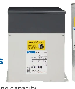
RANGE AT A GLANCE
Choose the right configuration.
Share supply voltage, load or motor details, control requirements, enclosure conditions and required accessories for model selection.
Capacitors
Detuned reactors
Thyristor switching
APFC controllers
ASVG
Active harmonic filters
MANUFACTURER REFERENCE / August 2026
Details, down to
the catalog number.
Browse the supplied specification pages. Published MRP is a dated manufacturer reference; request a current Nova quote and confirm the tax basis and pack size.
ESP Lauritz Knudsen Price List (1).pdf ↗ · PDF pages 95–102
8 catalog pages
PDF page 95 Power Quality Solutions
Extracted reference text; use the original PDF to check column alignment, variants and price units.
Power Quality Solutions
Power Factor Correction Capacitors [8532]
Heavy Duty HD Plus Super
Standard Duty Heavy Duty APP LTXL Ultra Heavy Duty
Gas Filled
Parameters
Cylindrical Box Cylindrical Box Cylindrical Cylindrical Box Cylindrical Box
Over current
withstand 1.5 x In 1.5 x In 1.8 x In 1.8 x In 2.0 x In 2.5 x In 2.5 x In 3 x In 3 x In
capability
Operating
0.45 W/kVAr 0.45 W/kVAr 0.5 W/kVAr 0.5 W/kVAr 0.45 W/kVAr 0.45 W/kVAr 0.5 W/kVAr 0.45 W/kVAr 0.5 W/kVAr
losses
Peak Inrush
current
withstand 200 x In 200 x In 250 x In 300 x In 300 x In 350 x In 300 x In 500 x In 500 x In
capability
Number of
switching
operations 5000 5000 7500 8000 10000 15000 10000 18000 20000
per year
Max. 55OC 55OC 55OC 55OC 55OC 65OC 55OC 65OC 70OC
Temperature
Operating life 100000 hrs. 100000 hrs. 130000 hrs. 150000 hrs. 180000 hrs. 200000 hrs. 200000 hrs. 300000 hrs. 300000 hrs.
Standard Duty Capacitors
Features
› Finger proof terminal in Cyl capacitor
› 150% continuous current carrying capacity
› Self-Healing property
› Soft resin as coolant
› Inbuilt Over Pressure Disconnector (OPD)
M.R.P.
Type
kVAr
Rating
Voltage
(V)
(`) Heavy Duty Capacitors
per kVAr
Features
1 to 25 440 299
Cylindrical › 180% continuous current carrying capacity
1 to 6 kVAr - Series : LTCCF 1.2 to 27.7 480 299
7.5 to 33.1 kVAr - Series : LTCCD › Finger proof terminal in Cyl capacitor
1.3 to 33.1 525 299 › Self-Healing property
Box
1 to 50 440 383 › Soft resin as coolant
1 to 6 kVAr - Series : LTBCF 11.1 to 27.7 480 383 › Inbuilt over pressure disconnector (OPD)
7.5 to 33.1 kVAr - Series : LTBCD › Low losses
13.2 to 33.1 525 383
M.R.P.
kVAr Voltage
Type (`)
Rating (V)
per kVAr
HD Plus Gas Filled Capacitor 1 to 4 572
Features 5 to 15 440 V 526
› High inrush current carrying capacity 300 x In 20 to 30 512
› Inert gas as coolent (Non-flammable) Cylindrical Series:
1.2 to 4.4* 572
› Finger proof terminal in Cyl capacitor LTCCH
› Self-Healing property 5.5 to 16.6 480 V 526
› Inbuilt Over Pressure Disconnector (OPD) 22.1 to 27.7 512
› Long life 1.3 to 5.3* 572
6.6 to 16.6 525 V 526
M.R.P.
kVAr Voltage 20 to 33.1 512
Type (`)
Rating (V)
per kVAr
1 to 4 733
7.5 to 15 623 440 V
440 5 to 15 634
20 & 25 579
20 to 50 621
7.5 to 15 623
480 Box Series:
Cylindrical Series: LTCCN 20 to 30 579 LTBCH 5.5 to 15 634
480 V
7.5 to 15 623 20 to 27.7 621
525
20 to 33.1 579 6.6 to 15 634
525 V
20 to 33.1 621
* Now smaller rating also available in Heavy Duty Cylindrical
Lauritz Knudsen, 15.08.2026 88PDF page 96 Power Quality Solutions
Extracted reference text; use the original PDF to check column alignment, variants and price units.
Power Quality Solutions
Super Heavy Duty APP Capacitors
Capacitors Features
Features › High over current withstand capacity 2.5 x In
› High over current withstand capacity 2.5 x In
› High Inrush current withstand capacity 300 x In
› High Inrush current withstand capacity 350 x In
› Glazed ceramic bushing
› Finger proof Sigut terminal in Cyl capacitor
› Tinned Copper studs
M.R.P.
Type
kVAr Voltage › Corrosion proof stainless steel Earthing pad
Rating (V) (`)
per kVAr
M.R.P.
kVAr Voltage
3 to 5 860 Type (`)
Rating (V)
per kVAr
7.5 to 15 703
440 V 5 to 15 1079
20 & 25 665 440 V
20 to 50 1044
1.2 to 5.5 860
Cylindrical Series: Box 5.5 to 13.8 1079
11.1 & 15 480 V 703 480 V
LTCCR Series: LTBCP 16.6 to 55.3 1044
20 to 27.7 665
6.6 & 13.2 1079
1.3 to 5 860 525 V
16.6 to 66.2 1044
6.6 to 15 525 V 703
20 to 33.3 665
LTXL - Ultra Heavy Duty Capacitors
Features
› High over current withstand capacity 3 x In Ordering Information for Capacitors
› High Inrush current withstand capacity 500 x In C - Cylindrical, B - Box
› Glazed ceramic bushing (In box type capacitor)
› Lower thermal impedance
› Designed to operate at temperature up to 70oC Duty: D/F – Standard**
› Corrosion proof stainless steel Earthing pad H - Heavy
N - Gas Filled
kVAr Voltage M.R.P. R - Super Heavy
Type (`)
Rating (V) P - APP
per kVAr
U - Ultra Heavy
5 to 15 1660
440V
20 & 25 1633
Sample ratings
Cylindrical 7.5 to 15 1660
Series : LTCCU 480V
20 1633 01 - 1 kVAr
kVAr
7.5 to 15 1660 07 - 7.5 kVAr
525V Rating
20 1633
10 - 10 kVAr
5 to 15 1848
440V 12 - 12.5 kVAr
20 to 50 1812
7.5 to 15 1848
Voltages:B - 440V, C - 480V, M- 525V
Box
Series: LTBCU 480V
20 to 30 1812 ** F - 1 to 6 kVAr. D - 7.5 kVAr & above
7.5 to 15 1848
20 to 33.1
525V
1812
L T C 3 2 Catalogue Number
kVAr ratings
Capacitor
Series 440 V 480 V 525 V
LTCCF 1, 2, 3, 4, 5, 6 1.2, 2.2, 3.3, 4.4, 5.5 1.3, 2.6, 3.9, 5.3, 6.6
LTBCF 1, 2, 3, 4, 5, 6 - -
LTCCD/LTBCD 7.5, 8.33, 10, 12.5, 15, 20, 25, 30* 11.1, 13.8, 16.6, 22.1, 27.7 13.2, 16.6, 20, 26.5, 30, 33.1
LTCCH 1, 2, 3, 4, 5, 7.5, 10, 12.5, 15, 20, 25, 30 1.2, 2.2, 3.3, 4.4, 5.5, 11.1, 13.8, 16.6, 22.1, 27.7 1.3, 2.6, 3.9, 5.3, 6.6, 13.2, 16.6, 20, 26.5, 30, 33.1
LTBCH 1, 2, 3, 4, 5, 7.5, 8.33, 10, 12.5, 15, 20, 25, 30, 50 5.5, 11.1, 15, 20, 25, 27.7 6.6, 13.2, 15, 20, 25, 30, 33.1
LTCCN 7.5, 8.33, 10, 12.5, 15, 20, 25 7.5, 12.5, 15, 20, 25, 30 7.5, 12.5, 15, 20, 25, 30, 33.1
LTCCR 3, 4, 5, 7.5, 8.33, 10, 12.5, 15, 20, 25 1.2, 2.2, 3.3, 4.4, 5.5, 11.1, 15, 20, 25, 27.7 1.3, 2.6, 3.9, 5, 6.6, 13.2, 15, 20, 25, 30, 33.3
LTBCP 5, 7.5, 10, 12.5, 15, 20, 25, 50 5.5, 11.1, 13.8, 16.6, 22.1, 27.7, 55.3 6.6, 13.2, 16.6, 20, 26.5, 30, 33.1, 66.2
LTCCU 5, 7.5, 8.33, 10, 12.5, 15, 20, 25 7.5, 10, 12.5, 15, 20 7.5, 10, 12.5, 15, 20
LTBCU 5, 7.5, 8.33, 10, 12.5, 15, 20, 25, 30, 50 7.5, 10, 12.5, 15, 20, 25, 30 7.5, 12.5, 15, 20, 25, 30, 33.1
*Only LTBCD is available at 30 kVAr
Lauritz Knudsen, 15.08.2026 89PDF page 97 Power Quality Solutions
Extracted reference text; use the original PDF to check column alignment, variants and price units.
Power Quality Solutions
Detuned Reactors, 440 V, 50 Hz [8504]
Features
› Copper & Aluminium wound reactors
› H-class insulation
› Lower operating losses
› 180% linearity*
› Thermal cut off
› High Quality Factor
7% Copper Reactor 7% Aluminium Reactor 14% Copper Reactor 14% Aluminium Reactor
kVAr
Rating M.R.P. (`) M.R.P. (`) M.R.P. (`) M.R.P. (`)
Cat. No. Cat. No. Cat. No. Cat. No.
Per Unit Per Unit Per Unit Per Unit
1 LTFR0701B2 15821 LTAL0701B2 9733 LTFR1401B2 30755 LTAL1401B2 16062
2 LTFR0702B2 17277 LTAL0702B2 10616 LTFR1402B2 33528 LTAL1402B2 17493
3 LTFR0703B2 19585 LTAL0703B2 12024 LTFR1403B2 38025 LTAL1403B2 19821
4 LTFR0704B2 20817 LTAL0704B2 12783 LTFR1404B2 40427 LTAL1404B2 21085
5 LTFR0705B2 23373 LTAL0705B2 13822 LTFR1405B2 43710 LTAL1405B2 24124
10 LTFR0710B2 31927 LTAL0710B2 19617 LTFR1410B2 61958 LTAL1410B2 34314
12.5 LTFR0712B2 36028 LTAL0712B2 21936 LTFR1412B2 67971 LTAL1412B2 39308
15 LTFR0715B2 41851 LTAL0715B2 26320 LTFR1415B2 74783 LTAL1415B2 46966
20 LTFR0720B2 46350 LTAL0720B2 29294 LTFR1420B2 86616 LTAL1420B2 53387
25 LTFR0725B2 47256 LTAL0725B2 29857 LTFR1425B2 95122 LTAL1425B2 54818
50 LTFR0750B2 79216 LTAL0750B2 46489 LTFR1450B2 153681 LTAL1450B2 77441
75 LTFR0775B2 117745 LTAL0775B2 68475 LTFR1475B2 222318 LTAL1475B2 115138
100 LTFR0700B2 153209 LTAL0700B2 94093 LTFR1400B2 297019 LTAL1400B2 155251
* Prices of 200% linearity reactors are available on request.
For industries with High Voltage Harmonics, special solutions are available on request. Contact your nearest sales office for the customised solutions.
Selection of capacitors for detuned harmonic filter application
Step Size &
With 7% detuned reactor With 14% detuned reactor
440 V
Reactor rating 480 V Capacitor 525 V Capacitor 525 V Capacitor
(kVAr) Capacitor series (kVAr) Capacitor series (kVAr)
(kVAr)
1 LTCCF, LTCCH, LTCCR 1.2 1.3 LTCCF, LTCCH, LTCCR 1.3
2 LTCCF, LTCCH, LTCCR 2.2 2.6 LTCCF, LTCCH, LTCCR 2.6
3 LTCCF, LTCCH, LTCCR 3.3 3.9 LTCCF, LTCCH, LTCCR 3.9
LTCCF, LTCCH 5.3 LTCCF, LTCCH 5.3
4 4.4
LTCCR 5 LTCCR 5
LTCCF, LTCCH, LTCCR, LTBCH, LTBCP 5.5 6.6 LTCCF, LTCCH, LTCCR, LTBCH, LTBCP 6.6
5
LTCCN, LTCCU, LTBCU 7.5 7.5 LTCCN, LTCCU, LTBCU 7.5
LTCCD, LTCCH, LTCCR, LTBCD, LTBCH, LTBCP 11.1 13.2 LTCCD, LTCCH, LTCCR, LTBCD, LTBCH, LTBCP 13.2
10
LTCCN, LTCCU, LTBCU 12.5 12.5 LTCCN, LTCCU, LTBCU 12.5
LTCCN, LTCCR, LTCCU, LTBCH, LTBCU 15 15 LTCCN, LTCCR, LTCCU, LTBCH, LTBCU 15
12.5
LTCCD, LTCCH, LTBCD, LTBCP 13.8 16.6 LTCCD, LTCCH, LTBCD, LTBCP 16.6
LTCCN, LTCCR, LTCCU, LTBCH, LTBCU 20 LTCCD, LTCCN, LTCCH, LTCCR, LTCCU,
15 20 20
LTCCD, LTCCH, LTBCD, LTBCP 16.6 LTBCD, LTBCH, LTBCP, LTBCU
LTCCN, LTCCR, LTBCH, LTBCU 25 25 LTCCN, LTCCR, LTBCH, LTBCU 25
20 LTCCD, LTCCH, LTBCD, LTBCP 22.1 26.5 LTCCD, LTCCH, LTBCD, LTBCP 26.5
LTCCU 7.5 + 15 2 x 12.5 LTCCU 2x12.5
LTCCD, LTCCH, LTCCR, LTBCD, LTBCH, LTBCP 27.7 LTCCD, LTCCN, LTCCH, LTCCR,
33.1 30
25 LTBCU, LTCCN 30 LTBCD, LTBCH, LTBCP, LTBCU
LTCCU 12.5 + 15 15 + 20 LTCCU (10+20)
LTCCD, LTCCH, LTCCR, LTBCD, LTBCH 2 x 27.7 LTCCD, LTCCN, LTCCH, LTCCR,
2 x 33.1 2 x 30
LTBCU, LTCCN 2 x 30 LTBCD, LTBCH, LTBCP, LTBCU
50
LTCCU 2 x (12.5 + 15) 2 x (15 + 20)
LTCCU 3 x 20
LTBCP 55.3 66.2
LTCCD, LTCCH, LTCCR, LTBCD, LTBCH 3 x 27.7 LTCCD, LTCCN, LTCCH, LTCCR,
3 x 33.1 3 x 30
LTBCU, LTCCN 3 x 30 LTBCD, LTBCH, LTBCP, LTBCU
75
LTCCU 3 x (12.5 + 15) 3 x (15 + 20)
LTCCU (4 x 20) + 10
LTBCP 27.7 + 55.3 33.1 + 66.2
LTCCD, LTCCH, LTCCR, LTBCD, LTBCH, LTBCP 4 x 27.7 LTCCD, LTCCN, LTCCH, LTCCR,
4 x 33.1 4 x 30
LTBCU, LTCCN 4 x 30 LTBCD, LTBCH, LTBCP, LTBCU
100
LTCCU 4 x (12.5 + 15) 4 x (15 + 20)
LTCCU 6 x 20
LTBCP 2 x 55.3 2 x 66.2
Lauritz Knudsen, 15.08.2026 90PDF page 98 Power Quality Solutions Thyristor Switchi
Extracted reference text; use the original PDF to check column alignment, variants and price units.
Power Quality Solutions                                                       Thyristor Switching Module, 440V 50Hz [8538]


Capacitor Duty Contactors - Type MO C [8536]
                                                                              Features
Features                                                                      › High Peak Inverse Voltage (PIV) - 2.2 kV
› Conforms to IS / IEC 60947-4-1 & IEC 60947-4-1                              › Inbuilt control supply voltage
› Delatching type early make contacts                                         › Auto thermal cut off
› Separate termination for damping resistors                                  › LEDs for various status/fault indications
› Encapsulated damping resistor assembly                                      › Ambient Temperature -10° C to 55° C
› Common coil for 50 & 60Hz application                                       › No moving parts
› Low pick-up VA consumption                                                  › On-site self test logic
› RoHS compliant                                                              › Low operating losses
                                                                              › 2 Nos Aux Contact outputs for fault and status
        kVAr Rating               Built-in                            Std.
                                                        M.R.P. (`)
 Size     @ 440V,       Type     Auxiliary   Cat. No.                 Pkg.
                                                         Per Unit
         3Ph, 50Hz               Contacts                            (Nos.)
                                                                                      kVAr Rating                                           M.R.P. (`)
              3        MO C3       1NO       CS96146      3480         1                                            Cat. No.
                                                                                                                                             Per Unit
              5        MO C5       1NO       CS96127      3700         1
                                                                                          10                    CS92049OOOO                     33245
            8.5       MO C8.5      1NO       CS96320      4800         1
                                                                                          25                    CS92050OOOO                     47424
             10       MO C10       1NO       CS96156      4910         1
                                                                                          50                    CS92051OOOO                     54317
 Fr 1      12.5       MO C12.5     1NO       CS96321      5180         1
                                                                              Note (TSM): Above prices include Quick Discharge Resistors (QDR)
             15       MO C15       1NO       CS90019      6980         1
             20       MO C20       1NO       CS90021      7770         1
             25       MO C25       1NO       CS96322      8370         1      Note (MOC):
             30       MO C30$      1NO       CS96148     13330         1      1) For ordering add-on aux. contact block, please refer page No. 8
             40       MO C40       1NO       CS96147     22120         1      2) For ordering suffix, please refer page No.10
                                                                              3) For ordering spare coils, please refer page No. 11
 Fr 2        50       MO C50       1NO       CS96324     24830         1
                                                                              4) Standard coil voltage : 240V, 50/60 Hz
             60       MO C60$      1NO       CS96149     25820         1      5) For ordering MO C surge suppressor, please refer page No. 9
             75       MO C75       1NO       CS96150     30870         1
                                                         33220                  If using 16 sq mm cable use of spreader link kit is mandatory
 Fr 3        85       MO C85       1NO       CS96157                   1
                                                                                For ordering spreader link kit, Please refer page No.9
           100        MO C100$     1NO       CS96158     33870         1      $ Spreader link along with phase barrier included in packing


                                                                                                                   Lauritz Knudsen, 15.08.2026           91
PDF page 99 APFC Controller [8538]
Extracted reference text; use the original PDF to check column alignment, variants and price units.
APFC Controller [8538]

etaSMART and etaULTRA Controllers are compatible for Sites with or without a Solar plant.

                            Site without Solar Plant                                                                     Site with Solar Plant


                                                    2 Quadrant Operation                                                                                      4 Quadrant Operation
                                                     of APFC Controller                                                                                        of APFC Controller


                           CT                                                                                           CT


                  Load                    APFC Panel                                             Load                     Solar Plant                APFC Panel


Enable 4 Quadrant setting in etaSMART and etaULTRA for site with Solar Plant.

                                                                                                          Cascading (Master - Slave configuration)
                                                                                                          for APFC panel with more than 16 steps
etaULTRA - APFC Controller - 3 CT inputs
Features

                                                                                                                                        +
› 3 Phase Current and Voltage measurement
› PF display - 3 Digit after decimal
› Individual harmonics measurement up to 31st order
› Dual PF setting for Mains - DG application
› Communication through Inbuilt MODBUS RS-485 Protocol
                                                                                                              4 Quadrant Operation suitable for
› Suitable for LT as well as HT side sensing
                                                                                                                 Solar Powered installations
                                 No. of steps             No. of steps
                                (For Contactor           (For Thyristor               Voltage Input                                                                M.R.P. (`)
 Model Name                                                                                                      Cat No.                      Size
                                  switching)               switching)                                                                                               Per Unit

 etaULTRA 8R                          8                        0                                             CS91050OOOO                                              31900

 etaULTRA 16R                        16                        0                                             CS91051OOOO                                              42790
                                                                                      110 / 415 V                                           144 x 144
 etaULTRA 14T+2R                      2                       14                                             CS91053OOOO                                              44740

 etaULTRA 8T+8R                       8                        8                                             CS91054OOOO                                              44740

Last Two Contacts can be programmed for Capacitor Switching / Alarm Function / Fan Control


etaSMART - APFC Controller - 1 CT input
Features
› Simple and Smart Controller
› Auto programming function available
› CT secondary - 1 / 5 Amp site selectable
› Measurement of Total harmonics distortion of                                                                4 Quadrant Operation suitable for
  current and voltage up to 13th order harmonics                                                                 Solar Powered installations

etaSMART T - APFC Controller for                                                           etaSMART R - APFC controller for
Thyristor Switching with 1 CT input                                                        Contactor switching with 1 CT input
  No. of steps                                                             M.R.P.            No. of steps                                                                M.R.P.
                                                  Single     Voltage                                                                             Single      Voltage
 (for Thyristor     Size           Cat. No.                                  (`)            (For Contactor     Size            Cat. No.                                    (`)
                                                 CT input     Input                                                                             CT input      Input
   switching)                                                              Per Unit           Switching)                                                                 Per Unit
       8          144 x 144     CS91614OOOO                                26800                      4       96 x 96        CS90884OOOO                                  12760

      12          144 x 144     CS91615OOOO      1/ 5 Amp     415 V        33350                      6       96 x 96        CS90885OOOO                                  14520

      15          144 x 144     CS91616OOOO                                38990                      8       96 x 96        CS90902OOOO                                  17110
                                                                                                                                                1/ 5 Amp      415 V
One separate relay contact is available for Alarm                                                   12       144 x 144       CS90903OOOO                                  28290
                                                                                                    14       144 x 144       CS90904OOOO                                  34960
                                                                                                    16       144 x 144       CS90905OOOO                                  38070

                                                                                           Last Two Contacts can be Programmed for Capacitor Switching /
                                                                                           Alarm Function / Fan Control

                                                                                                                                        Lauritz Knudsen, 15.08.2026             92
PDF page 100 ASVG Features
Extracted reference text; use the original PDF to check column alignment, variants and price units.
ASVG Features
› Dynamic Stepless PF correction, Load balancing &
  Harmonic Mitigation
› Suitable for DPF & TPF improvement
› Harmonic Mitigation up to 15th Order
› Fast response time of 50 µsec
› Scalable architecture for future expansion
› Lower thermal losses
› Communicable –Inbuilt MODBUS RS485 Protocol
› Wall mount/ Rack Mount Modules                                      3P3W ASVG (415 V,-25%+15%)   3P4W ASVG (415 V,-25%+10%)
                                                             kVAr
› True Hybrid Solution Compatibility                        Rating

                                                                                  *                             *
                                                              30     ASVG0030H3WD2                 ASVG0030H4WD2
                                                                                  *                             *
Hybrid controller                                             50     ASVG0050H3WD2                 ASVG0050H4WD2
                                                                                  *                             *
                                                              100    ASVG0100H3WD2                 ASVG0100H4WD2
› Intuitive Touchscreen display
                                                              150    ASVG0150H3WD2*                ASVG0150H4WD2*
› Easy installation & programming
                                                              30      ASVG0030N3RD2                ASVG0030N4RD2
› 18 Ports to connect Capacitor banks (Thyristor & Cap.
  duty Contactor Switching)                                   50      ASVG0050N3RD2                ASVG0050N4RD2

› Alarm and Event Management                                  100     ASVG0100N3RD2                ASVG0100N4RD2

› Bar Chart Visualization                                     150     ASVG0150N3RD2                ASVG0150N4RD2
                                                                Hybrid Controller / HMI


                                                          * ASVG module with inbuilt HMI
PDF page 101 Power Quality Solutions
Extracted reference text; use the original PDF to check column alignment, variants and price units.
Power Quality Solutions

Active Harmonic Filter (AHF) [8543]


                              AHF


 ACTIVE HARMONIC FILTER - MODULE                                                ACTIVE HARMONIC FILTER
 Features                                                                       Features
 › Reduces THD within IEEE - 519 limits                                         › Reduces THD within IEEE - 519 limits
 › Harmonic Mitigation, Dynamic Stepless PF correction & Load                   › Harmonic mitigation up to 50th Order
   balancing                                                                    › Harmonic Mitigation, Dynamic Stepless PF correction &
 › Advanced 3 Level Inverter topology                                             Load balancing
 › Harmonic Mitigation up to 51st Order                                         › With complete panel enclosure
 › Fast response time of 50 µsec                                                › Up to 1000 Amp in a single enclosure
 › Lower thermal losses                                                         › Customizable to withstand in extreme environment
 › Scalable architecture for future expansion                                   › Communicable – Inbuilt MODBUS RS485 Protocol
 › Communicable –Inbuilt MODBUS RS485 Protocol                                  › Modular Design allowing for future expansion
 › Wall mount/ Rack Mount Modules                                               › Ease of Monitoring using Touch Screen HMI
 › True Hybrid Solution Compatibility                                           › Fully Customized as per site condition**


               3P3W AHF (415 V,-25%+15%)         3P4W AHF (415 V,-25%+10%)
   Ampere                                                                       Contact your nearest sales office for customized solution.
    Rating                          M.R.P. (`)                     M.R.P. (`)
                  Cat. No.*                         Cat. No.*
                                     Per Unit                       Per Unit
                                                                                                  3 Phase 3 wire AHF              3 Phase 4 wire AHF
                           *                                 *
     30        AHF0030H3WD2                      AHF0030H4WD2                     Ampere     Without Neutral Compensation     With Neutral Compensation
                           *                                 *                     Rating                   M.R.P. (`)                       M.R.P. (`)
     50        AHF0050H3WD2                      AHF0050H4WD2                                 Cat. No.*                       Cat. No.*
                           *                                 *                                               Per Unit                         Per Unit
    100        AHF0100H3WD2                      AHF0100H4WD2
                                                                                    30      AHF030431D2                     AHF030441D2
    150        AHF0150H3WD2*          On         AHF0150H4WD2*       On
                                    Request                        Request          60      AHF060431D2                     AHF060441D2
     30        AHF0030N3RD2                      AHF0030N4RD2
                                                                                    100     AHF100431D2                     AHF100441D2
     50        AHF0050N3RD2                      AHF0050N4RD2
                                                                                    125     AHF125433D2                     AHF125443D2
    100        AHF0100N3RD2                      AHF0100N4RD2
                                                                                    150     AHF150433D2                     AHF150443D2
    150        AHF0150N3RD2                      AHF0150N4RD2
                                                                                    200     AHF200433D2                     AHF200443D2
    Hybrid Controller / HMI
                                                                                    250     AHF250433D2         On          AHF250443D2         On
                                     AHFHC18R00T                                                              Request                         Request
                                                                                    300     AHF300433D2                     AHF300443D2

                                     AHFHC00R18T                                    400     AHF400433D2                     AHF400443D2
                                                                  On
                                                                Request             500     AHF500433D2
                                     AHFHC09R09T
                                                                                    600     AHF600433D2

                                       AHFHMI007                                    750     AHF750433D2

                                                                                   1000     AHF000433D2
 * AHF module with inbuilt HMI
                                                                                *Standard CAT No. Configuration       Cable Entry – Top/Cable Alley

                                                                                **Customisable options available
                                                                                IP Class – IP 40/IP 42/IP 54
                                                                                Conformal Coating - (3C3)


                                                                                                                   Lauritz Knudsen, 15.08.2026            94
PDF page 102 * Note: Hybrid Panel Combination - ASVG + APFC & AHF + APFC
Extracted reference text; use the original PDF to check column alignment, variants and price units.
* Note: Hybrid Panel Combination - ASVG + APFC & AHF + APFC


Suggested Step Ratings for APFC Panels

Panel                                 No. of Electrical Steps (All       No. of      Panel                                  No. of Electrical Steps (All        No. of
       Physical Step
Rating                               Physical Possible Combination      Electrical   Rating Physical Step                  Physical Possible Combination       Electrical
       Size (kVAr)
(kVAr)                                Steps of Physical Steps)            Steps      (kVAr) Size (kVAr)                     Steps of Physical Steps)             Steps
  10   4+3+2+1                          4    1,2,3,4...8,9,10              10         120   50 + 25 + 20 + 15 + 4 + 2x3       7    3,4,6,7….114,116,117,120       85
  15   5+4+3+2+1                        5    1,2,3,4...13,14,15            15         125   50 + 2x25 + 15 + 4 + 2x3          7    3,4,6,7….119,121,122,125       55
  20   10 + 5 + 2x2 + 1                 5    1,2,3,4…18,19,20              20         130   50 + 2x25 + 20 + 4 + 2x3          7    3,4,6,7….124,126,127,130       60
  25   15 + 5 + 2x2 + 1                 5    1,2,3,4…23,24,25              20         135   2x50 + 15 + 10 + 4 + 2x3          7    3,4,6,7….129,131,132,135       65
  30   15 + 10 + 2x2 + 1                5    1,2,3,4…28,29,30              22         140   2x50 + 20 + 10 + 4 + 2x3          7    3,4,6,7….134,136,137,140       62
  35   20 + 10 + 2x2 + 1                5    1,2,3,4…33,34,35              23         145   2x50 + 25 + 10 + 4 + 2x3          7    3,4,6,7….139,141,142,145       65
  40   20 + 10 + 5 + 3 + 2              5    2,3,5,7…35,37,38,40           24         150   2x50 + 25 + 15 + 4 + 2x3          7    3,4,6,7….144,146,147,150       66
  45   25 + 10 + 5 + 3 + 2              5    2,3,5,7…40,42,43,45           24         155   2x50 + 25 + 15 + 3x5              7    5,10,15,20….145,150,155        31
  50   25 + 15 + 5 + 3 + 2              5    2,3,5,10…45,47,48,50          24         175   2x50 + 2x25 + 10 + 3x5            8    5,10,15,20….165,170,175        35
  55   25 + 15 + 10 + 3 + 2             5    2,3,5,10….50,52,53,55         25         200   2x50 + 3x25 + 15 + 2x5            8    5,10,15,20...190,195,200       40
  60   25 + 15 + 10 + 5 + 3 + 2         6    2,3,5,7….55,57,58,60          36         225   3x50 + 2x25 + 15 + 10             7    10,15,25,35...210,215,225      27
  65   25 + 2x15 + 5 + 3 + 2            6    2,3,5,7….60,62,63,65          35         250   3x50 + 3x25 + 15 + 10             8    10,15,25,35...235,240,250      30
  70   25 + 20 + 15 + 5 + 3 + 2         6    2,3,5,7….65,67,68,70          36         275   4x50 + 2x25 + 15 + 10             8    10,15,25,35...260,265,275      33
  75   2x25 + 15 + 5 + 3 + 2            6    2,3,5,7….70,72,73,75          39         300   100 + 2x50 + 3x25 + 15 + 10       8    10,15,25,35...285,290,300      36
  80   2x25 + 15 + 10 + 3 + 2           6    2,3,5,10….75,77,78,80         36         325   100 + 3x50 + 2x25 + 15 + 10       8    10,15,25,35...310,315,325      39
  85   50 + 20 + 5 + 4 + 2x3            6    2,3,5,6….80,81,82,85          44         350   100 + 4x50 + 25 + 15 + 10         8    10,15,25,35...335,340,350      42
  90   50 + 25 + 5 + 4 + 2x3            6    3,4,5,6….85,86,87,90          47         375   2x100 + 2x50 +2x25 + 15 + 10      8    10,15,25,35…360,365,375        45
  95   50 + 25 + 10 + 4 + 2x3           6    3,4,6,7….89,91,92,95          43         400   2x100 + 2x50 + 4x25               8    25,50,75,100…350,375,400       16
 100   50 + 25 + 15 + 4 + 2x3           6    3,4,6,7….94,96,97,100         44         425 2x100 + 3x50 + 3x25                 8    25,50,75,100…375,400,425       17
 105   50 + 25 + 15 + 5 + 4 + 2x3       7    3,4,5,6….100,101,102,105      85         450 2x100 + 3x50 + 4x25                 9    25,50,75,100…400,425,450       18
 110   50 + 25 + 15 + 10 + 4 + 2x3      7    3,4,5,6….104,106,107,110      65         475 2x100 + 4x50 + 3x25                 9    25,50,75,100…425,450,475       19
 115   50 + 25 + 2x15 + 4 + 2x3         7    3,4,6,7….109,111,112,115      65         500 2x100 + 5x50 + 2x25                 9    25,50,75,100…450,475,500       20

Note: Above mentioned steps are typical recommendations, suitable for most of the industries. For accurate compensation,
step size selection may have to be decided after studying load profile of that industry.                               Lauritz Knudsen, 15.08.2026                   95
No matching text found. Try a shorter model code or check the original PDF, including illustrated pages.
BEFORE YOU SPECIFY
Make an informed choice.
LET’S GET THE SPECIFICATION RIGHT
From your shortlist
to a clear quote.
Share the catalog number, rating and quantity. We’ll confirm the current price, availability and lead time.